Actuation · Mechanical design
CORActuator
An integrated robotic joint combining a 20:1 cycloidal transmission, hollow-shaft sensing, and a custom STM32 motor controller.
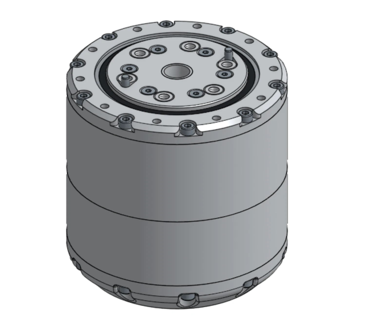
Joint architecture, gearbox and bearing design, mechanical prototyping, hollow-shaft sensing, and motor/controller integration.
Overview: an integrated joint
After a couple of years working on robotics, I had a clearer understanding of what the next actuator needed to deliver: manufacturability, cost-effective construction, integrated control, and high performance.
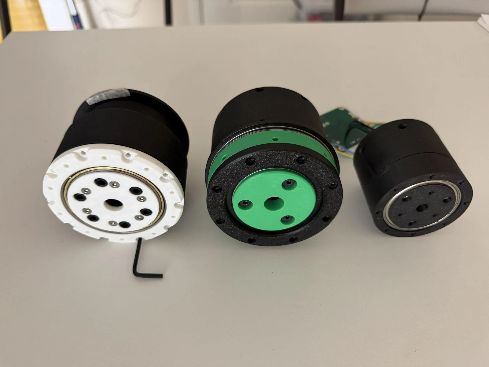
My earlier printed actuators established the gearing and packaging approach, but their construction was not robust enough for the next stage. CORA — Compact Open-source Robotic Actuator develops that work into a full-metal assembly with a hollow cable passage and integrated control.
The current design uses a 20:1 cycloidal reduction. The mechanical target is 20 Nm at 100 rpm, with an estimated bill of materials below USD $300 at quantity one. These are design targets and a prototype cost estimate; output torque, continuous duty, and thermal limits still require bench characterization.
Choosing a 20:1 cycloidal transmission
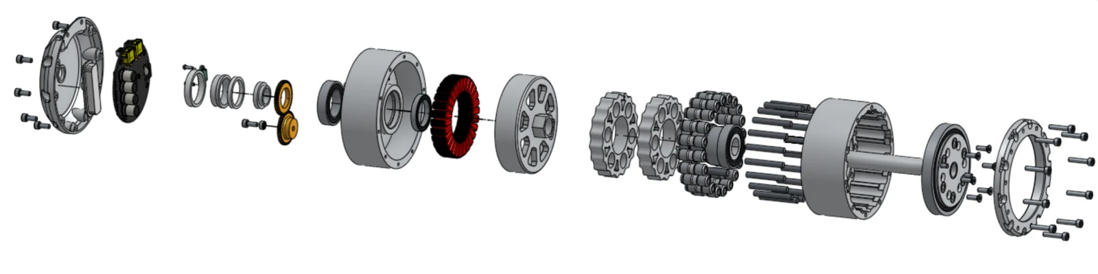
The transmission choice balanced reduction, backdrivability, backlash, and the cost of precision parts. The Wolfrom planetary arrangement in my earlier printed actuators offered a compact high ratio, but required several accurately matched gears. The cycloidal architecture concentrated the custom geometry in the discs and eccentric drive, with rollers carrying the contact loads.
I chose 20:1 to retain useful mechanical advantage without pushing reduction so high that friction and reflected inertia dominate joint behavior. Backdrivability matters for impedance control: the mechanism must respond to external loads as well as transmit commanded torque. The cycloidal design still needs tight profile and alignment control; its low-backlash potential depends on the manufactured assembly.
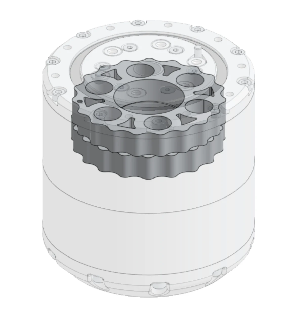
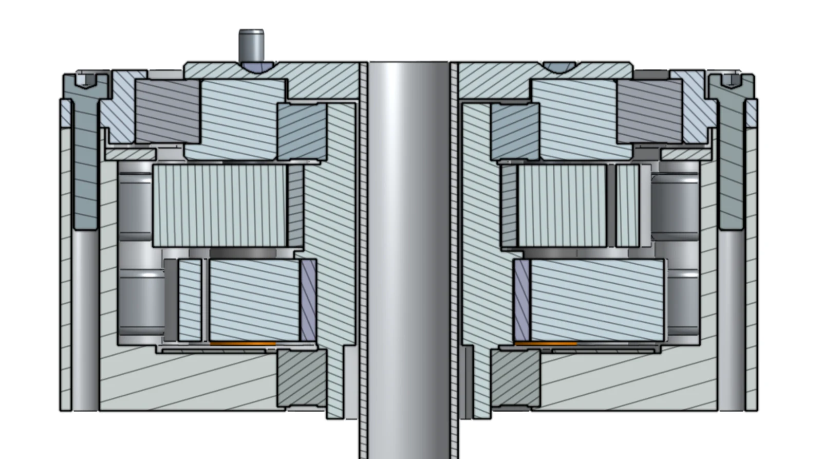
The two aluminum discs are phased 180° apart to balance the eccentric motion. Machined prototype parts and grinding experiments address profile accuracy and fit. Rollers replace sliding bushings at the working contacts to reduce friction and wear, while the eccentric shaft preserves the central cable passage. Shaft surface finish, hardness, and bearing fits remain critical manufacturing details.
The X-contact bearing
The output bearing influences four things at once: load capacity, precision, cost, and weight. A joint in a robot arm can be pushed along its axis, loaded sideways, and subjected to a bending moment. The bearing arrangement has to support the combination, not just the motor’s rotation.
In my earlier actuators, a combination of radial and thrust bearings kept the cost down. The weak point was the axial load path in the opposite direction. Imagine pulling the assembly apart from the output: the clamped carrier still depended on what the lower radial bearing and its retention could support. Adding a flange kept parts in place, but did not by itself create a stiff, bidirectional output support.
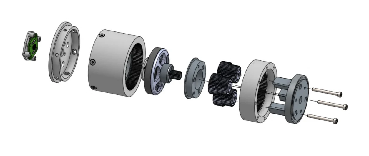
Angular-contact bearings address combined radial and axial loading through inclined contact geometry. A single-row bearing generally supports axial load in one direction, so an opposing pair can support both directions.
An X-contact, or four-point-contact, bearing packages opposing contact directions into one bearing. Its race geometry provides four potential ball-contact points in section. Suitable thin-section designs support radial, axial, and moment loads while taking less axial space than a pair of angular-contact bearings. This made the arrangement attractive for CORA’s output, although preload, housing stiffness, and the selected bearing’s ratings still determine the actual joint stiffness. SKF thin-section bearing reference.
The Thrifty Bot’s X-contact bearing is an example from the FRC parts ecosystem. Crossed-roller bearings were another option, but price and sourcing were significant constraints for this prototype. I chose the four-point-contact approach to balance the output-support requirements with the cost and weight of the complete actuator.
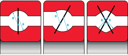
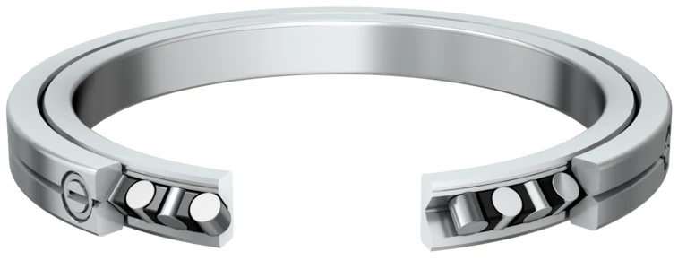
Reference images: Kaydon contact geometries and Schaeffler crossed-roller ring.


Selecting a motor around the joint requirements
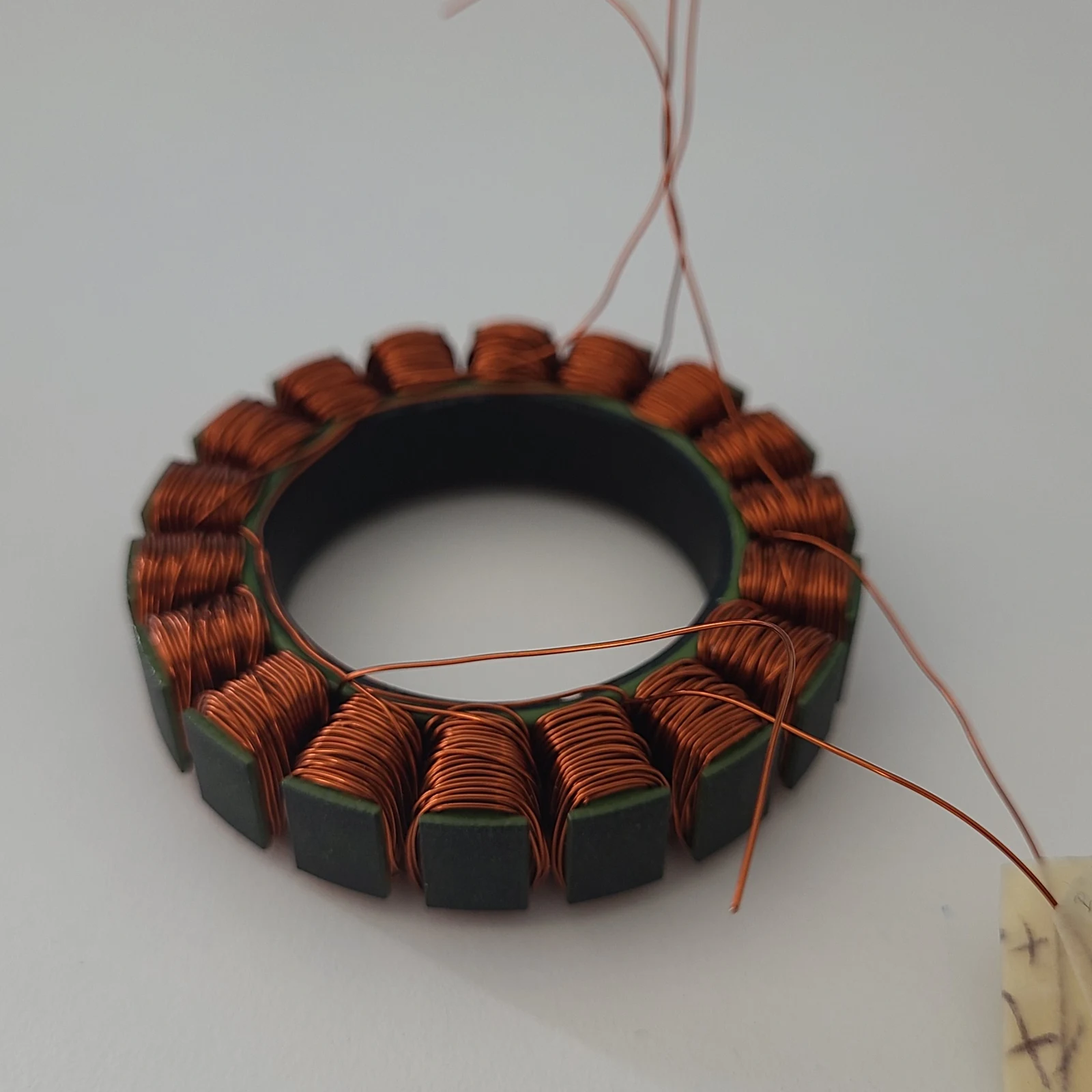
The first builds used off-the-shelf BLDC motors. They simplified integration, but often meant working around an existing motor specification instead of optimizing the actuator as a whole. I then bought stators and magnets to experiment with building my own motors, including the hand-wound prototype below.
The custom builds gave me control over the geometry, but theoretical calculations alone were not enough to characterize their performance. That led me to compare them with commercial frameless motors: supplied rotor and stator assemblies that integrate directly into the joint without a separate motor housing and bearing package. Both custom and off-the-shelf options are part of the evaluation in my BLDC Design Studio.
The selection starts at the output shaft. 20 Nm at 100 rpm is approximately 209 W of mechanical output. With a 20:1 reduction, the ideal motor operating point is 1 Nm at 2,000 rpm. Gearbox losses increase the required motor torque above that value, and motor losses add heat that the housing must reject. This makes sustained power within the available volume the central constraint; a peak-torque number alone does not size the joint.
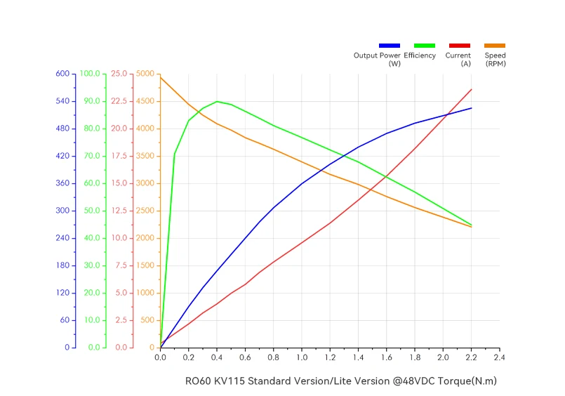
The curve makes the tradeoff visible: increasing load raises current and reduces speed, while efficiency varies across the operating range. Motor selection therefore has to cover the required torque–speed point and the heat generated there. The manufacturer's rated torque also provides a useful first screen before testing the motor inside the actuator.
Inrunner or outrunner?
Two commercial references make the packaging choice concrete:
| Manufacturer specification | RI60 KV120 inrunner | RO60 KV115 Lite outrunner |
|---|---|---|
| Outer diameter × axial length | 60 × 23 mm | 70.5 × 15 mm |
| Mass | 155.9 g | 195 g |
| Rated / peak torque | 0.57 / 1.63 Nm | 0.8 / 2.4 Nm |
The RI60 fits a smaller diameter and places its stationary outer stator against the housing, creating a direct conduction path. The RO60 is shorter axially and offers higher listed torque, but its rotating outer rotor leaves the stator heat path through the internal support. These are packaging and thermal-path considerations for CORA.
I selected the CubeMars outrunner for its higher listed torque and compatibility with my existing assembly. The next step is to measure its torque–speed performance and thermal behavior inside the actuator.
Specifications and chart: CubeMars RI60 and CubeMars RO60 Lite.
Cooling within the actuator envelope
The enclosure is the shared heat sink for the motor and controller. Heat has to travel from the windings through the stator and its mounting interface into the housing, while the power stage needs its own conductive interface to that same shell. A larger external surface only helps once those internal paths carry heat effectively.
The next housing iteration needs external cooling channels and fins to increase exposed area within the joint envelope. Their spacing must leave room for air to move between them; tightly packed grooves add little useful cooling if the air remains trapped. Stator contact, controller contact, housing geometry, and airflow will be evaluated together under sustained load.
Surface treatment is another design variable. Anodizing raises aluminum's thermal emissivity, improving radiative heat rejection relative to a bright bare surface. Black anodizing is a finish option, but the visible dye color is not the source of that benefit. Conduction through the mounting interfaces and convection from the housing remain central to the thermal design. Advanced Thermal Solutions’ anodization reference.
Integrating the controller into the joint
The CORA-L controller closes the loop between the motor, encoders, and robot. Its circular board fits within the actuator housing while preserving the central cable passage. Phase connections sit at the board edge, and paired CAN connectors allow successive joints to share the communication bus. The housing also provides a heat path for the power electronics, so board placement and mechanical packaging have to be designed together.
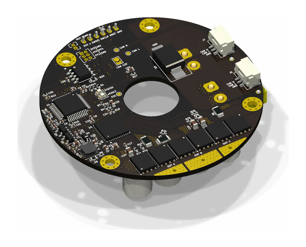
The STM32G473 runs field-oriented current control, with slower speed and position loops above it. Motor feedback supports commutation; output and turn sensing support joint feedback. This makes the actuator a controllable joint with a common communication interface. The electronics, current-sensing tradeoffs, firmware architecture, and CAN update workflow are covered in the CORA-L motor controller project.
Sensing both joint position and accumulated rotation
CORA’s sensing architecture addresses three quantities: motor angle for commutation, output angle for joint feedback, and accumulated rotation. Off-axis sensing keeps the cable passage open. The custom output-sensor experiments use analog sine/cosine signals, while the hardware collection also includes an MA732-based off-axis revision.
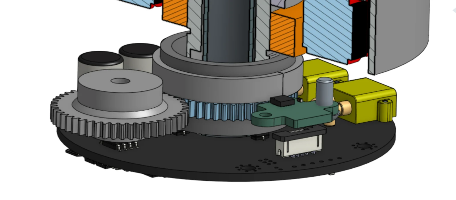
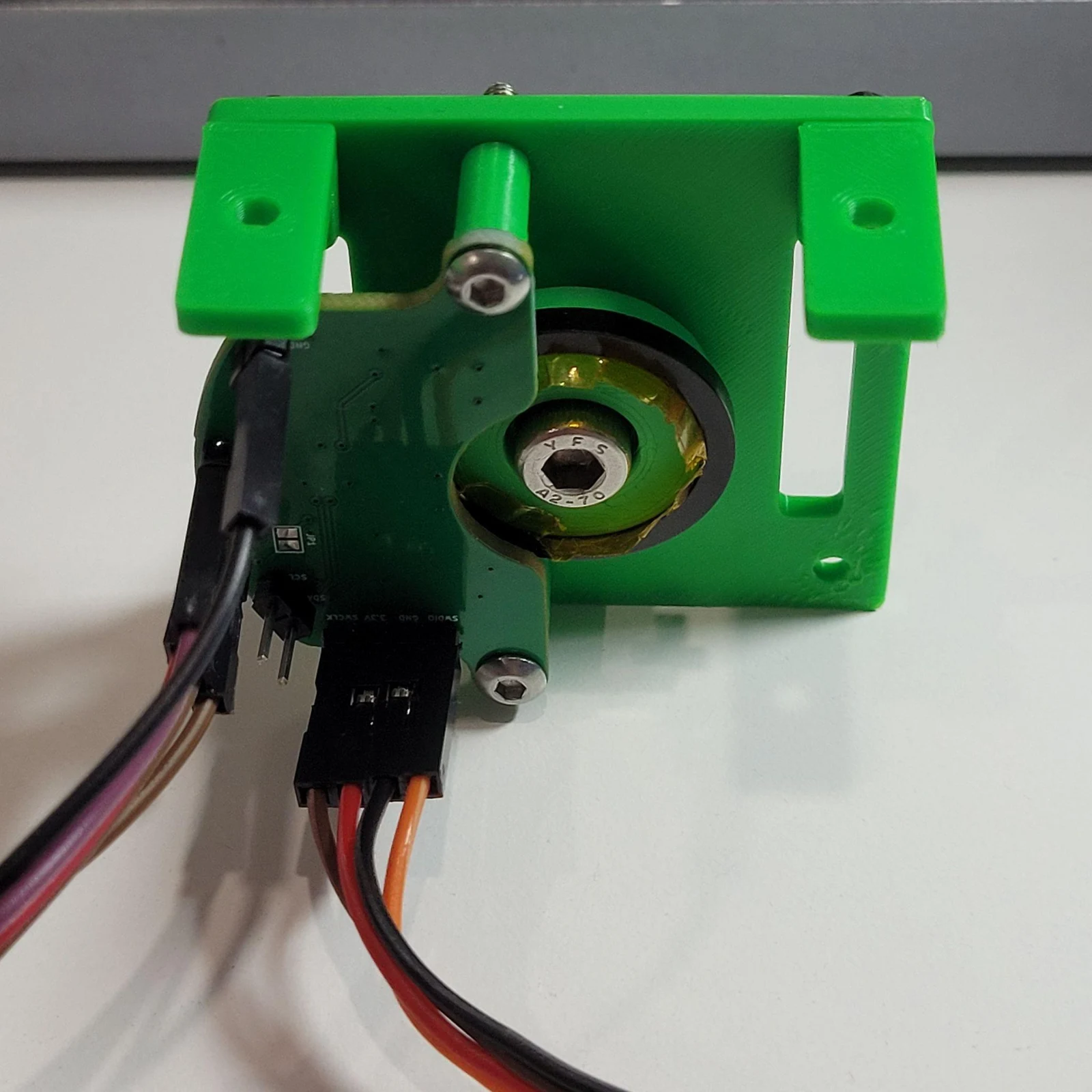
The Vernier gearing concept uses two slightly different gear periods. Their relative phase identifies the turn within the repeat interval, while the angular sensor resolves position within that turn. This provides a route to multi-turn sensing without a backup battery. Input-angle nonlinearity requires a correction lookup table; reference sweeps and power-cycle tests must establish the completed system’s accuracy and turn reconstruction.
TODOs
- Finish disc manufacture and stackup checks, then measure backlash, output runout, backdriving torque, and loaded output torque.
- Validate encoder correction and Vernier turn reconstruction against a reference through reversals and power cycles.
- Add housing cooling channels and define the stator/controller thermal interfaces; measure enclosed temperatures under sustained load to establish the assembled joint’s continuous operating limits.
- Complete grease containment and sealing, then inspect the transmission after sustained loaded operation.
- Define the arm workspace and joint-load requirements, then use them to refine actuator sizing and joint configuration.
Power-stage bring-up, current calibration, and firmware validation are tracked with the controller project’s TODOs.