Motor design · Simulation
BLDC Design Studio
A motor-design workbench connecting winding geometry, nonlinear field analysis, drive electronics, and torque–speed performance.
Desktop application, shared motor models, FEMM and ngspice integration, and numerical validation.
Overview: designing the motor and drive together
A motor can look promising in CAD and still be a poor fit for the joint around it. More winding turns change the voltage requirement, more current creates heat, and the available torque changes with speed. While developing actuators, I wanted to evaluate those tradeoffs before committing to another winding or mechanical revision.
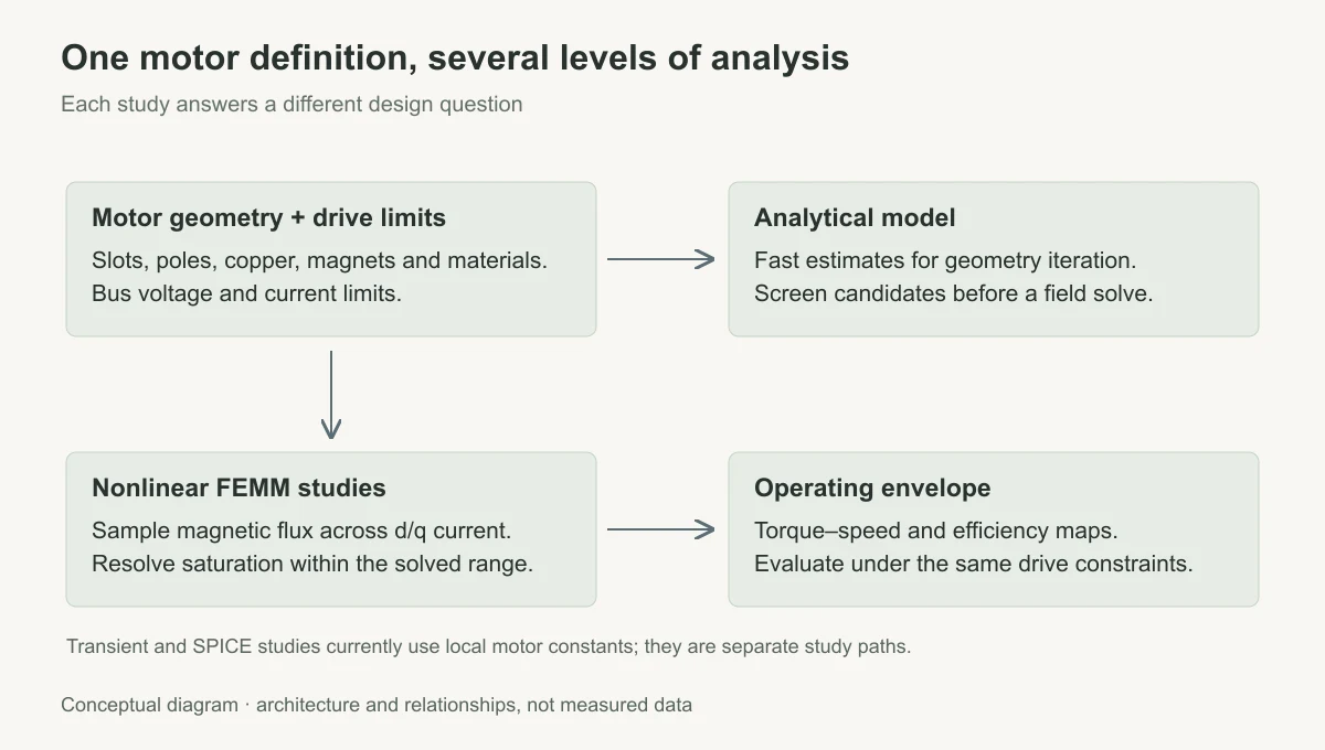
That became BLDC Design Studio: a workbench that connects the motor geometry to the drive electronics and operating envelope. The goal is to make a design decision traceable. When a torque curve changes, it should be possible to identify the geometry, material, or drive limit responsible for it.
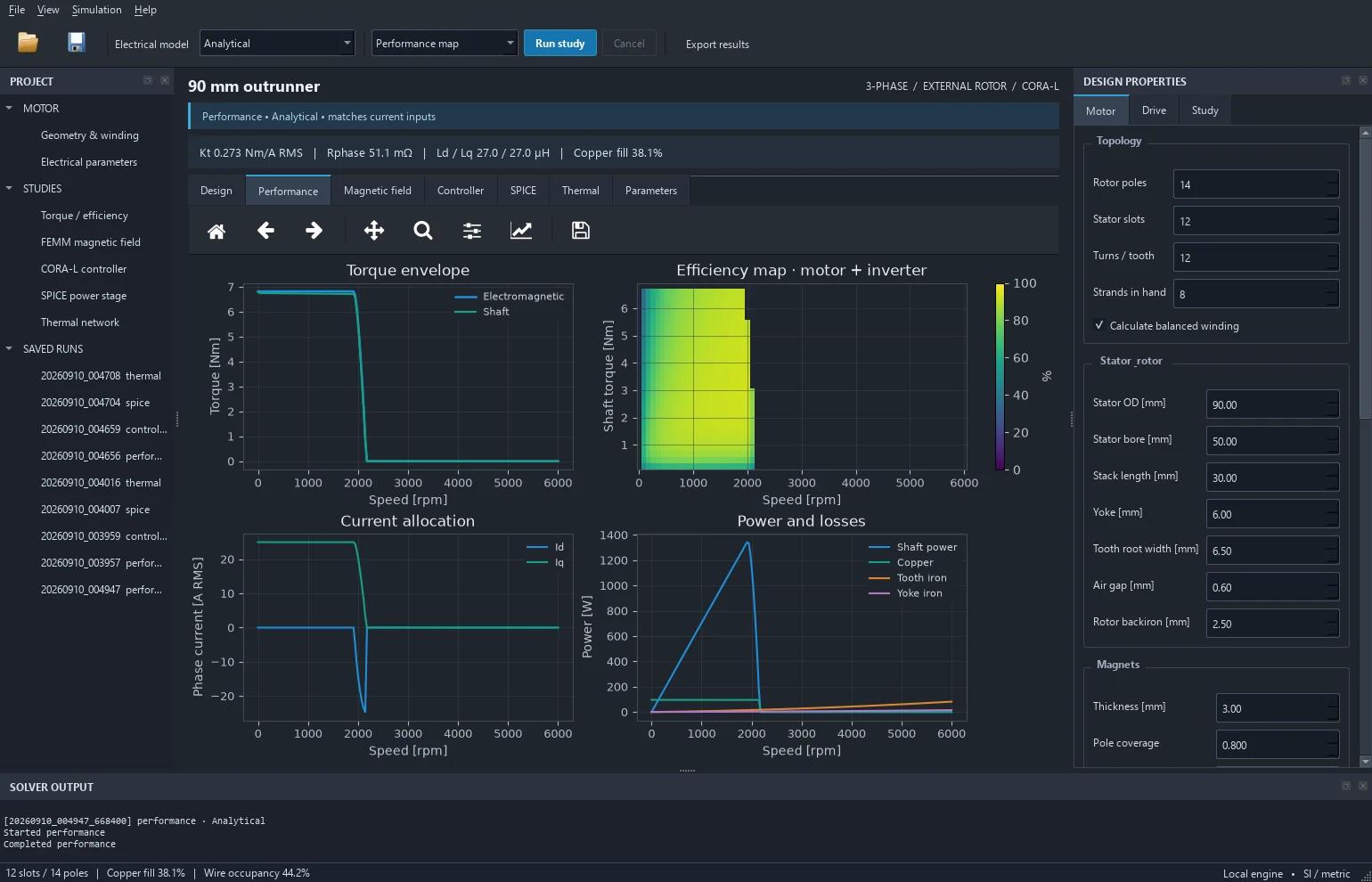
The inputs cover slot/pole count, stator and magnet dimensions, copper and enamel, lamination material, and drive limits. The workbench generates winding assignments, cross-sections, slot occupancy, material masses, electrical constants, torque-speed envelopes, and efficiency maps. Explicit peak/RMS and phase/line conventions prevent unit conventions from distorting the comparison.
Keeping the interface responsive during a solve
The desktop application uses Qt through PySide6 for dockable parameter panels, a project tree, geometry inspection, and plots. The original browser interface and the desktop app use the same physics models. Separating numerical code from widgets keeps interface changes independent of the motor model.
A field solve can take much longer than a parameter edit. Running it in the interface thread would make the whole application wait, including the controls needed to inspect progress. I separated long studies into isolated worker processes. A request captures the project and study options; the worker returns results and progress logs. FEMM and ngspice do not execute on the GUI thread, so their solve time does not freeze the workbench. Each study saves its input snapshot with the result for later comparison.
Choosing the right level of model
The first question is usually whether a geometry is worth pursuing at all. Analytical calculations are useful here because they are fast enough to compare many changes. A promising design then goes to nonlinear FEMM studies, where the magnetic material can saturate instead of behaving like an ideal constant-permeability core. A geometry fingerprint prevents a field solution from an older motor from being reused after dimensions or materials change.
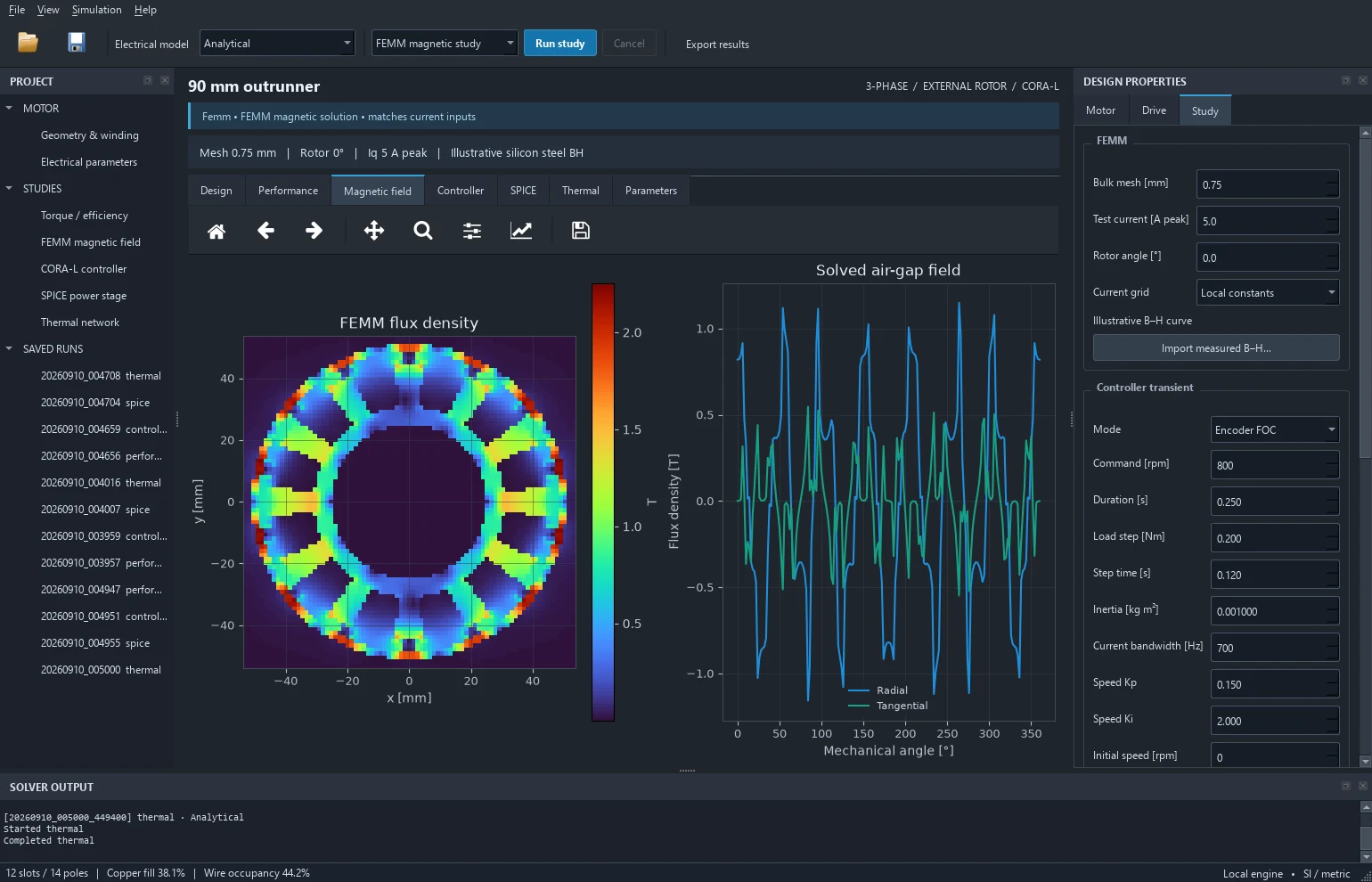
Steady-state studies solve 3 × 3, 5 × 5, or 7 × 7 grids of d/q current and interpolate the current-dependent flux. The performance calculation stays inside the solved range. The d/q axes describe current components relative to the rotor. Sampling several combinations captures how the magnetic response changes with loading. Increasing grid density costs solver time, but resolves that behavior in more detail than one fixed pair of inductances.
Connecting motor behavior to the controller
The transient studies include encoder FOC, sensorless EMF/PLL control, and six-step drive. Load steps, bus droop, voltage saturation, and observer angle error expose behavior that a steady-state torque curve cannot capture. The ngspice path adds switching behavior and a coupled mechanical motor state.
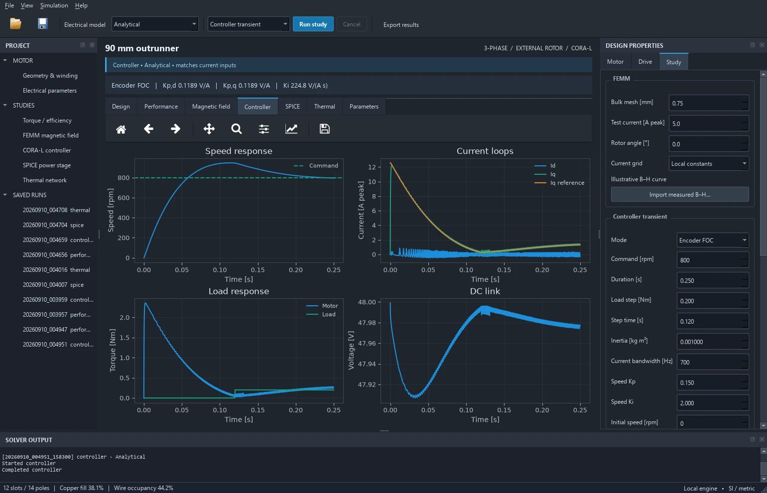
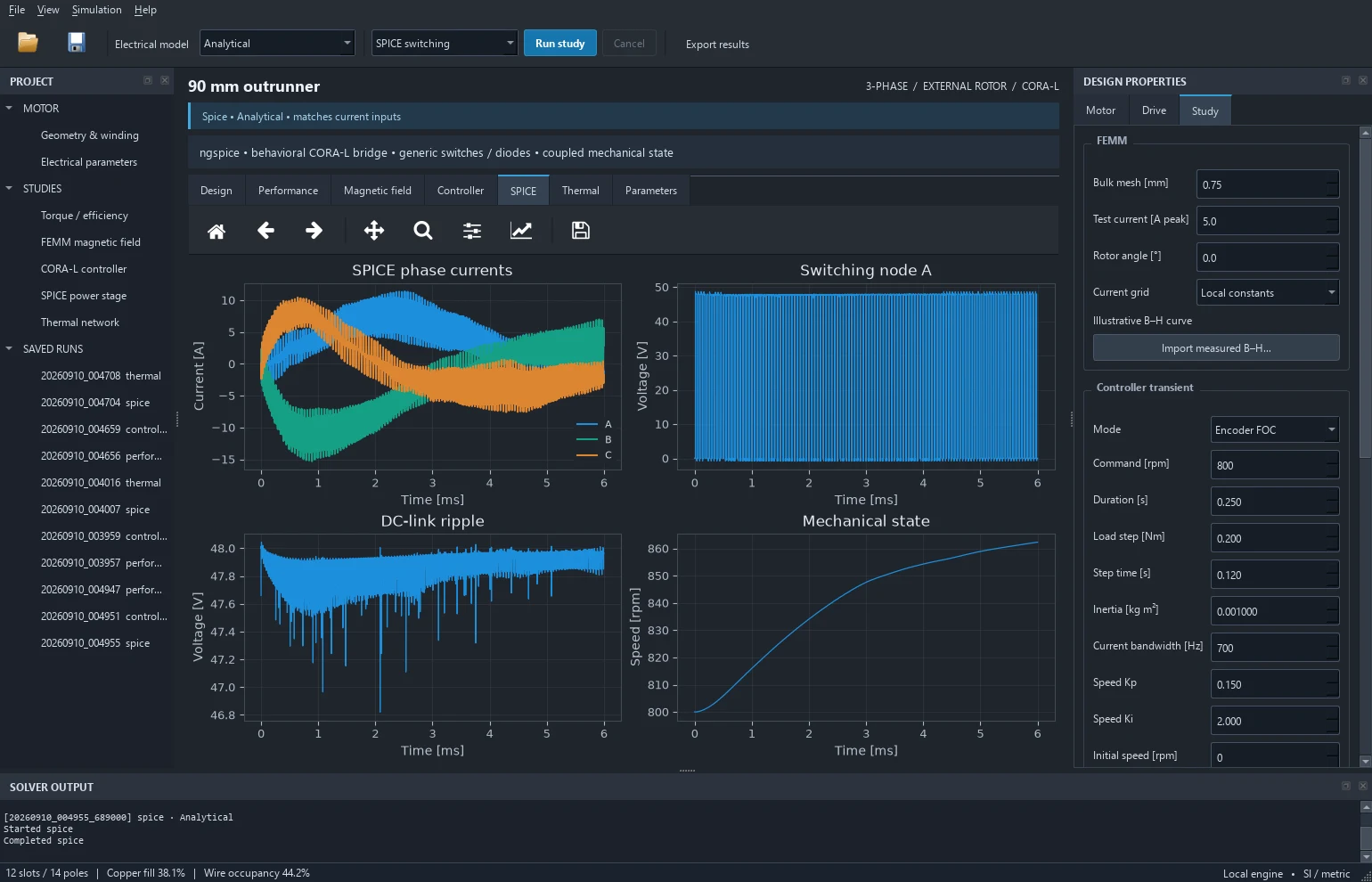
Nonlinear current grids feed the steady-state maps; dynamic and SPICE studies currently use local motor constants. The SPICE bridge is a behavioral power-stage model; running it does not execute the CORA firmware.
Investigating the RO60 inductance mismatch
A useful model also has to explain where it disagrees with a reference. In the RO60 reconstruction, the calculated inductance was well below the manufacturer’s value. One possible explanation was a definition mismatch: secant inductance describes the overall flux-to-current ratio, while differential inductance describes the local change around an operating point. I checked that distinction before changing the geometry to force a match. I ran eight additional nonlinear solves, perturbing the d/q currents around zero at ±0.5 A and ±0.25 A.
The smaller-perturbation terminal estimate was 192.542 µH, compared with the manufacturer's 395 µH. Halving the perturbation changed the calculated Jacobian by only 0.00203%. That result narrowed the investigation: the choice of static differential versus secant definition did not explain the missing inductance for that geometry and operating point.
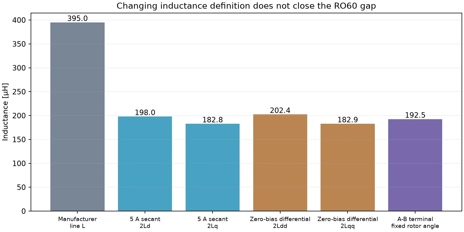
A dataset audit also identified synthetic samples, which are retained only as a rejection test. Physical calibration depends on measured material properties and bench data.
TODOs
- Resolve the RO60 geometry and winding assumptions against measured resistance, back-EMF, and inductance over rotor angle and frequency.
- Replace illustrative steel-loss and thermal parameters with measured data, then compare predictions with bench results.
- Add nonlinear transient lookup so controller studies can use the current-dependent flux model.
- Extend rotor-angle and mesh convergence studies, and add vendor switching models where device behavior matters.