Power electronics · Embedded control
CORA-L motor controller
A compact motor controller developed through component optimization and board revisions, with STM32G473 FOC, three-phase current sensing, and chainable power and CAN.
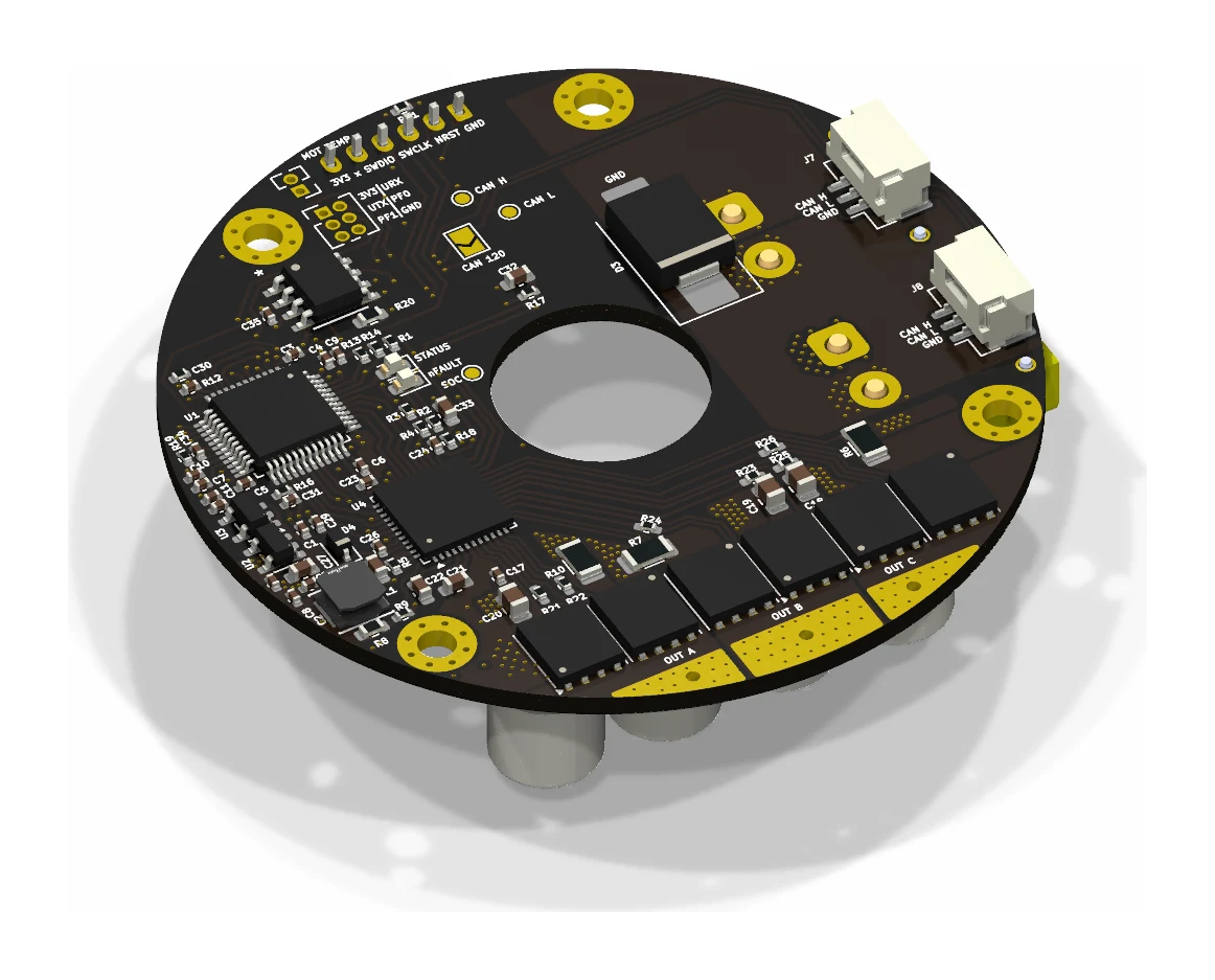
Controller PCB design and revision, MOSFET selection with the JLC/LCSC part-selection tool, current sensing, embedded control, and CAN tooling.
Overview: a controller built for the joint
CORA-L integrates motor control into the CORActuator joint. The circular board keeps the hollow shaft open for cables and combines the inverter, current sensing, encoder interfaces, and CAN in the actuator housing. The design evolved from my earlier CORA-V1 controller through component optimization, schematic corrections, and changes that make a chain of joints easier to wire and debug.
The implemented hardware and firmware are:
| Function | CORA-L implementation |
|---|---|
| Nominal bus | 36 V architecture |
| MCU | STM32G473CBT6 |
| Gate driver | DRV8323RS, with integrated buck regulator and three current-sense amplifiers |
| Three-phase bridge | Six BSC057N08NS3-G MOSFETs; 80 V device rating |
| Current sensing | Three 2 mΩ, 1 W, 1% shunts; 20/40 V/V firmware gain selection |
| Control cadence | 20 kHz PWM/current loop |
| Communications | Classical CAN at 1 Mbps, paired connectors, selectable termination |
| Power distribution | Two XT30 connectors on the common bus |
Optimizing MOSFET selection with the JLC part tool
MOSFET selection sets a large part of the controller’s loss, cost, and sourcing requirements. Low on-resistance reduces conduction loss, but gate charge and capacitance also affect the energy spent switching at each PWM cycle. The component search therefore has to account for the drive conditions as well as the package and supplier inventory.
I used my JLC/LCSC part-selection tool to turn that search into a repeatable comparison. The Python tools query a local component database, normalize catalog attributes and units, and collect electrical parameters alongside package, price, stock, and datasheet links. The Streamlit interface brings the reference device, alternatives, operating assumptions, and ranking into one view.
The MOSFET workflow separates suitability from optimization:
- Screen the electrical requirements. Set the minimum drain–source voltage and current requirements, inspect the package, and filter the candidates. The results retain constraint flags so an attractive score does not hide an unsuitable part.
- Compare loss contributions. The model accounts for on-resistance at elevated temperature, gate-drive energy, switching overlap, output capacitance, and reverse recovery. Bus voltage, nominal/peak current, PWM frequency, gate drive, and effective gate resistance are adjustable inputs.
- Rank the sourcing tradeoff. Performance, price, and stock receive adjustable weights. The interface also plots on-resistance against gate charge and exports the comparison for datasheet review.
This made the MOSFET tradeoff explicit: a lower-resistance part earns its place only when its switching burden, footprint, and cost also fit the controller. The tool exposes the assumptions used to fill missing catalog parameters, while preserving the original attributes and datasheet links for review. Its loss calculations are screening models used to rank alternatives under the same conditions.
The current CORA-L PCB specifies six Infineon BSC057N08NS3-G devices in TDSON-8 packages. Their 80 V drain–source rating provides device-level voltage margin around the 36 V bus architecture. Infineon specifies 5.7 mΩ maximum on-resistance at 10 V gate drive. The selected device and the adjustable gate resistors connect the catalog comparison to the inverter layout and switching setup. MOSFET specifications.
Correcting the earlier controller
The revision addressed specific electrical and bring-up problems in the first board.
Supply separation. CORA-L uses two TPS7A2033 regulators in place of a single regulator feeding both logic and analog rails. Separate regulators distribute the load and keep the analog supply separate from logic switching loads.
Gate-drive tuning. The earlier driver connected directly to the MOSFET gates. CORA-L adds an individual 10 Ω series resistor to each of the six gates. These components give each switching edge an explicit tuning point for controlling ringing and balancing transition speed against switching loss.
Current-sense layout and loss. The original board used 4 mΩ shunts. The new board uses 2 mΩ shunts and dedicated positive/negative sense nets at the driver inputs. Halving the resistance halves shunt dissipation at the same current; amplifier gain recovers the measurement sensitivity.
Chaining power and CAN between joints
Both controller generations provide two power connectors, allowing the bus to continue from one joint to the next. CORA-L retains that XT30 pass-through and changes the paired CAN connectors from 1.0 mm JST-SH to 1.25 mm JST-GH, keeping CAN-H, CAN-L, and ground on each connection.
The termination change is critical to chaining. The earlier board placed a fixed 120 Ω resistor across CAN-H and CAN-L. CORA-L puts the termination resistor behind a solder jumper, so it is enabled at the ends of the bus and left open on intermediate joints. Adding another actuator no longer adds another permanently connected termination resistor.
Together, the paired connectors and selectable termination make the board part of a multi-joint wiring system. Motor phases stay local to the actuator, while power and the communication bus continue along the robot.
Selecting the 2 mΩ shunt
The current-sense sweep compares resolution and clipping across shunt values and amplifier gains at 10 A nominal / 15 A peak. I selected 2 mΩ with 40 V/V gain for that operating point: the calculated resolution is 10.1 mA per ADC count, and 15 A uses 86% of the amplifier’s linear output swing. A shunt carrying 10 A RMS dissipates 0.20 W, half the loss of the earlier 4 mΩ value.
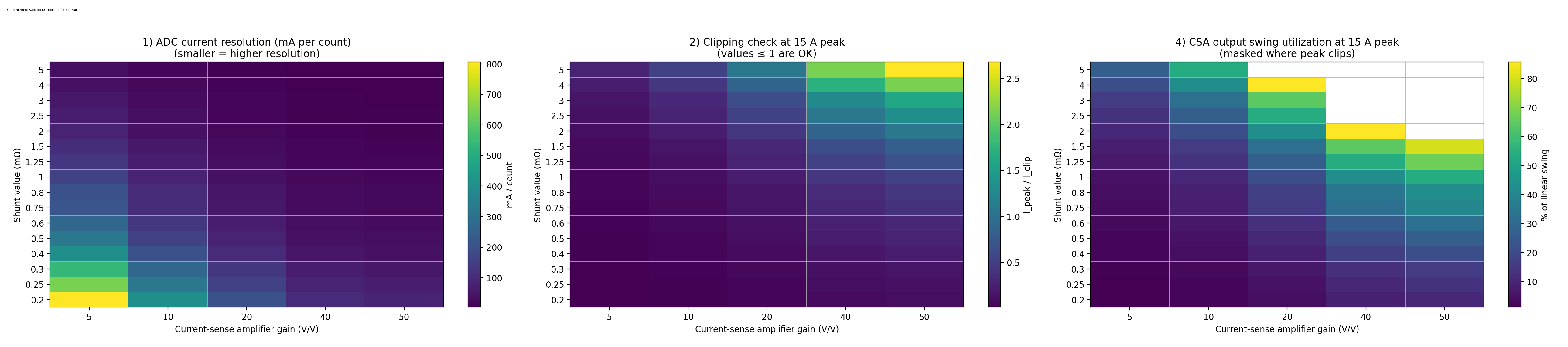
The firmware selects 20 or 40 V/V and reads back the driver gain to keep the current conversion consistent. At 20 V/V, the nominal current step doubles and the linear sensing range doubles. These are current-measurement specifications; sustained-load testing establishes the complete board’s continuous-current rating.
Firmware architecture: shared control, separate platforms
The firmware keeps reusable control mathematics separate from the STM32 peripheral drivers. Angle sensing, current measurement, and PWM sit behind small interfaces, so the embedded controller and host motor simulation share the same FOC and speed-control implementation.
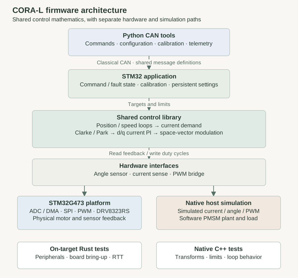
Native C++ tests cover transform round-trips, modulation, saturation, invalid numerical values, and mechanical/electrical speed conventions. A separate Rust crate uses on-target tests and RTT for peripheral bring-up. Host and MCU builds use separate build directories so their toolchain configuration stays independent.
From phase-current samples to PWM
The firmware runs a 20 kHz PWM/current-control cadence. Phase-current samples and rotor angle enter the Clarke/Park transforms, which express current in the rotating d/q frame. Current PI controllers calculate voltage commands, and space-vector modulation converts them into inverter duty cycles. Slower speed and position loops generate demand for the inner current loop.
Timing is part of the control problem. Current acquisition is tied to PWM timing so feedback corresponds to the low-side conduction interval. Encoder latency determines the age of the angle used for commutation. The implementation moves configuration polling and temperature conversion out of the fast path, uses a pipelined SPI encoder transfer, and instruments fast-loop execution time.
Calibration, configuration, and updates over CAN
A calibration state machine performs prechecks, resistance and inductance estimation, rotor locking, bidirectional sweeps, and back-EMF estimation. Progress and results are exposed over CAN. Configuration includes motor constants, control gains, electrical offset, encoder direction, node ID, and operating limits. Live RAM settings support tuning; flash-backed settings persist between power cycles.
The 16 KB bootloader receives application images over classical CAN at 1 Mbps and checks CRC32 before starting the application. Persistent configuration occupies a separate flash page. Shared message IDs, packed payloads, and configuration enums keep the Python tools aligned with the firmware. These tools provide the configuration and diagnostic interface for the integrated joint.
CAN FD bring-up
The board pairs the STM32G473's FDCAN peripheral with an MCP2562FD transceiver. The firmware frame abstraction supports payloads up to 64 bytes, and the platform driver handles the FD-format and bit-rate-switch flags. This provides the hardware and driver foundation for CAN FD's larger payloads and a faster data phase. Microchip CAN FD transceiver reference.
The application currently sets APP_CAN_CLASSIC_ONLY = true. Its nominal and data timing settings are identical, and the bootloader uses classical CAN at 1 Mbps. CAN FD support in the driver is therefore separate from the communication mode currently configured for bring-up.
The remaining bench-tool limitation is the USB adapter: I do not yet have a USB-to-CAN FD interface. The next step is to add that interface, configure distinct arbitration and data-phase timings, and verify 64-byte transmit/receive traffic with bit-rate switching. Bus-error monitoring and sustained traffic across chained controllers will establish the working configuration. The classical-CAN bootloader remains the firmware-update path.
TODOs
- Capture switching waveforms and tune the six gate resistors against overshoot, ringing, and switching loss.
- Measure phase-current offset, noise, and clipping across the 20/40 V/V gain settings; set gain-switch thresholds from the amplifier’s linear output range.
- Run sustained-load tests and publish continuous phase current against bus voltage, cooling conditions, and board temperature.
- Measure fast-loop execution time, ADC sampling skew, and encoder latency; complete the ADC trigger/rank redesign.
- Compare motor-calibration results with measured resistance, inductance, and back-EMF.
- Add a USB-to-CAN FD adapter and validate 64-byte frames, bit-rate switching, error handling, and sustained traffic across chained controllers.
- Exercise the chained CAN bus, command timeouts, configuration storage, and recovery from interrupted firmware updates.