Mechanism design · Prototyping
3D-printed robotic actuators
Successive cycloidal and planetary robotic joints, with parametric gearing, integrated sensing, and physical backdrivability tests.
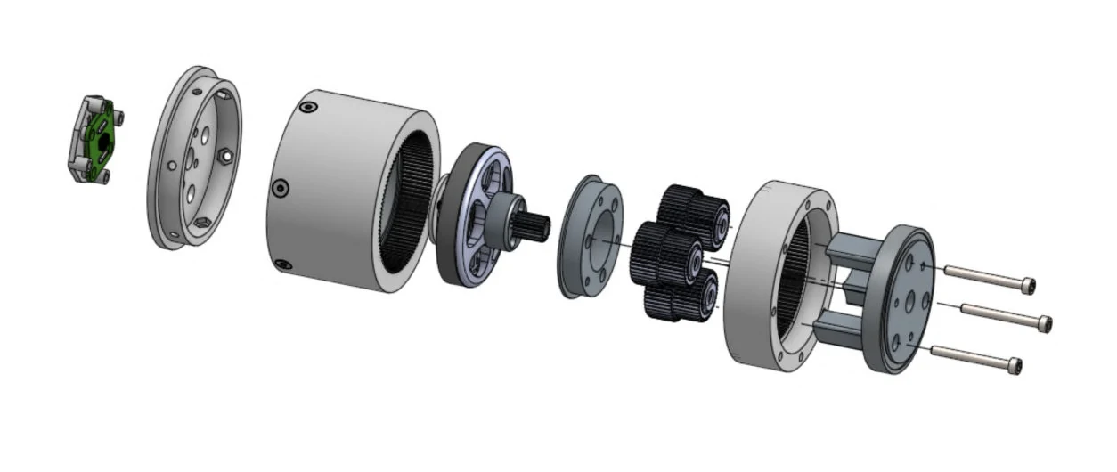
Parametric gear and housing design, prototype fabrication and assembly, and backdrivability evaluation.
Overview: an actuator affordable enough to use in every joint
A low-cost robot quickly becomes expensive if each joint needs a specialized actuator. These builds explored how much of a geared joint could be made with printed parts, a small BLDC motor, and accessible bearings. My priorities were compact packaging, useful reduction, backdrivability, and integrated sensing, with a cost that would make several joints practical.
The prototypes progressed through cycloidal and planetary arrangements. Each revision answered a different mechanical problem; the nominal gear ratio was only one part of making the assembly usable.
The first cycloidal prototype
The earlier version used cycloidal discs. I drew the disc profiles as parametric curves in SOLIDWORKS and designed the assembly around a 5010 BLDC motor with a 28:1 reduction. An eccentric input drives the discs against the surrounding contacts, while the output mechanism extracts their slower rotation. I built and tested the assembly to see how that geometry behaved with printed parts and real bearings. The resulting friction, package size, and assembly constraints guided the next version.
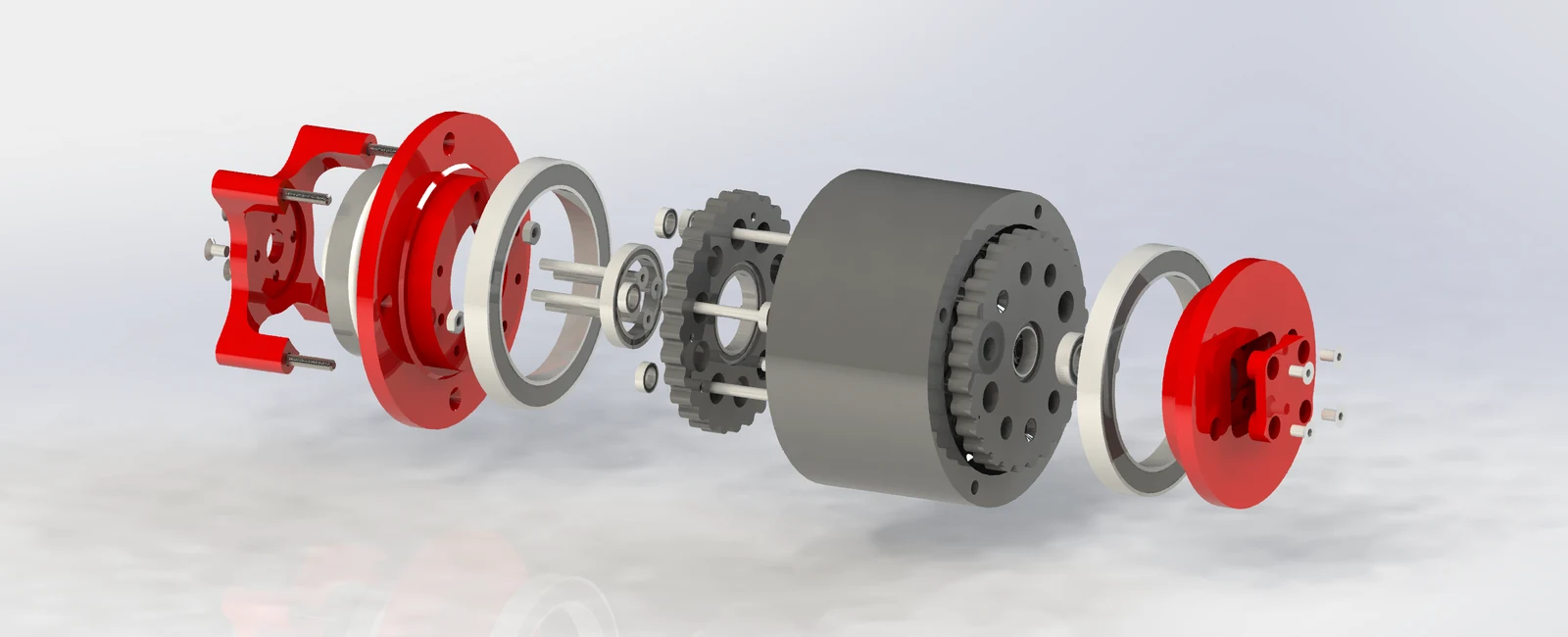
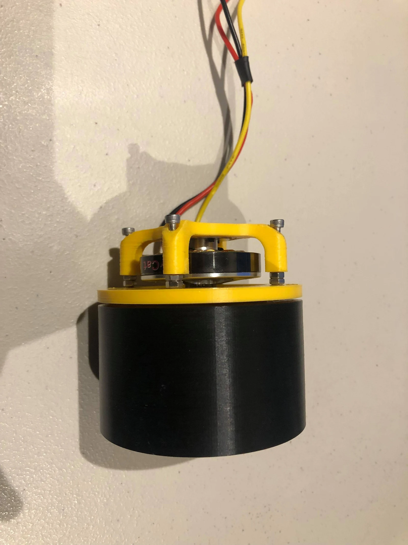
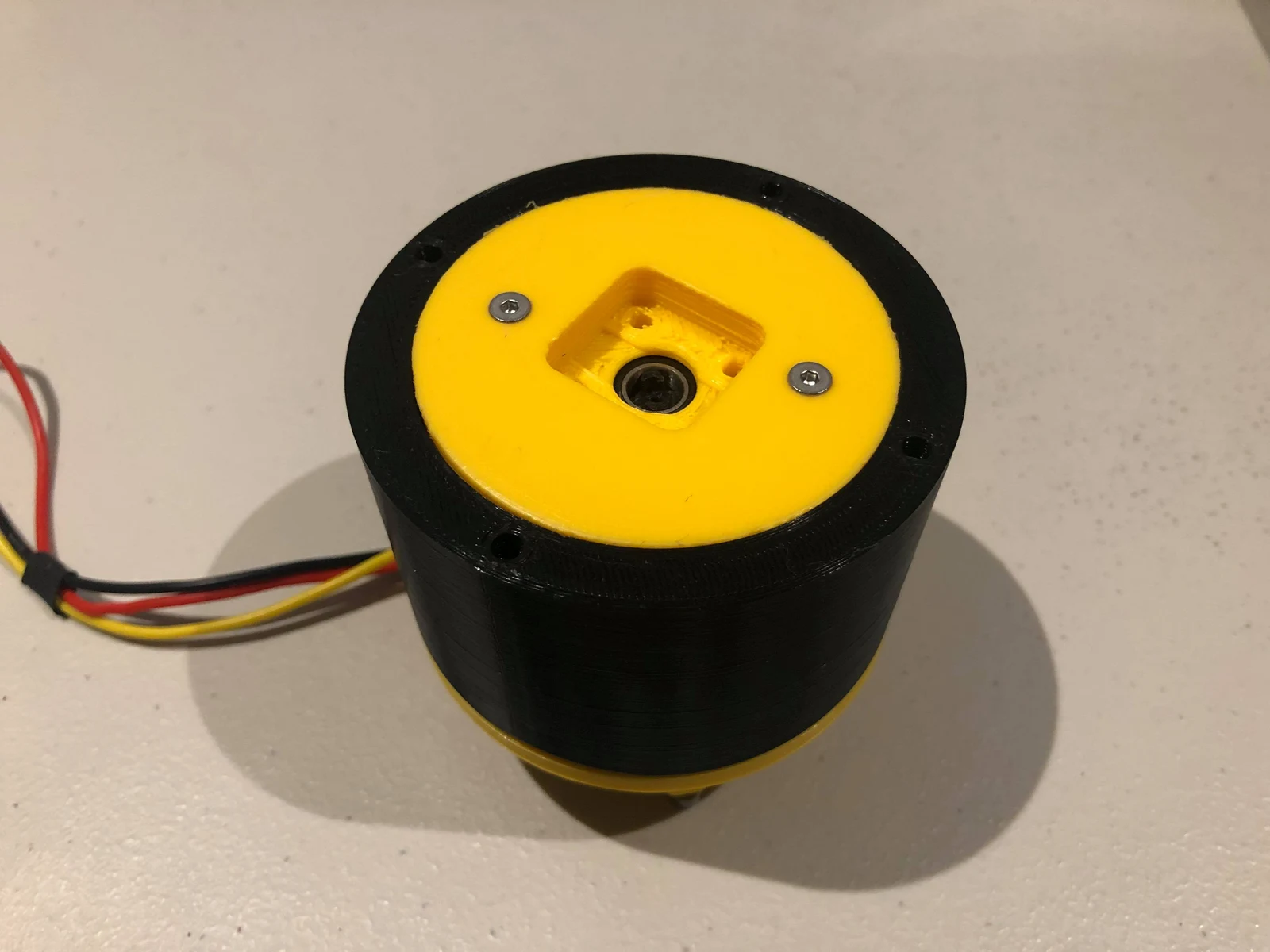
Why I moved to planetary gearing
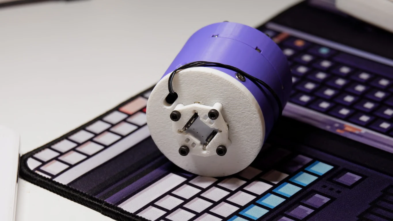
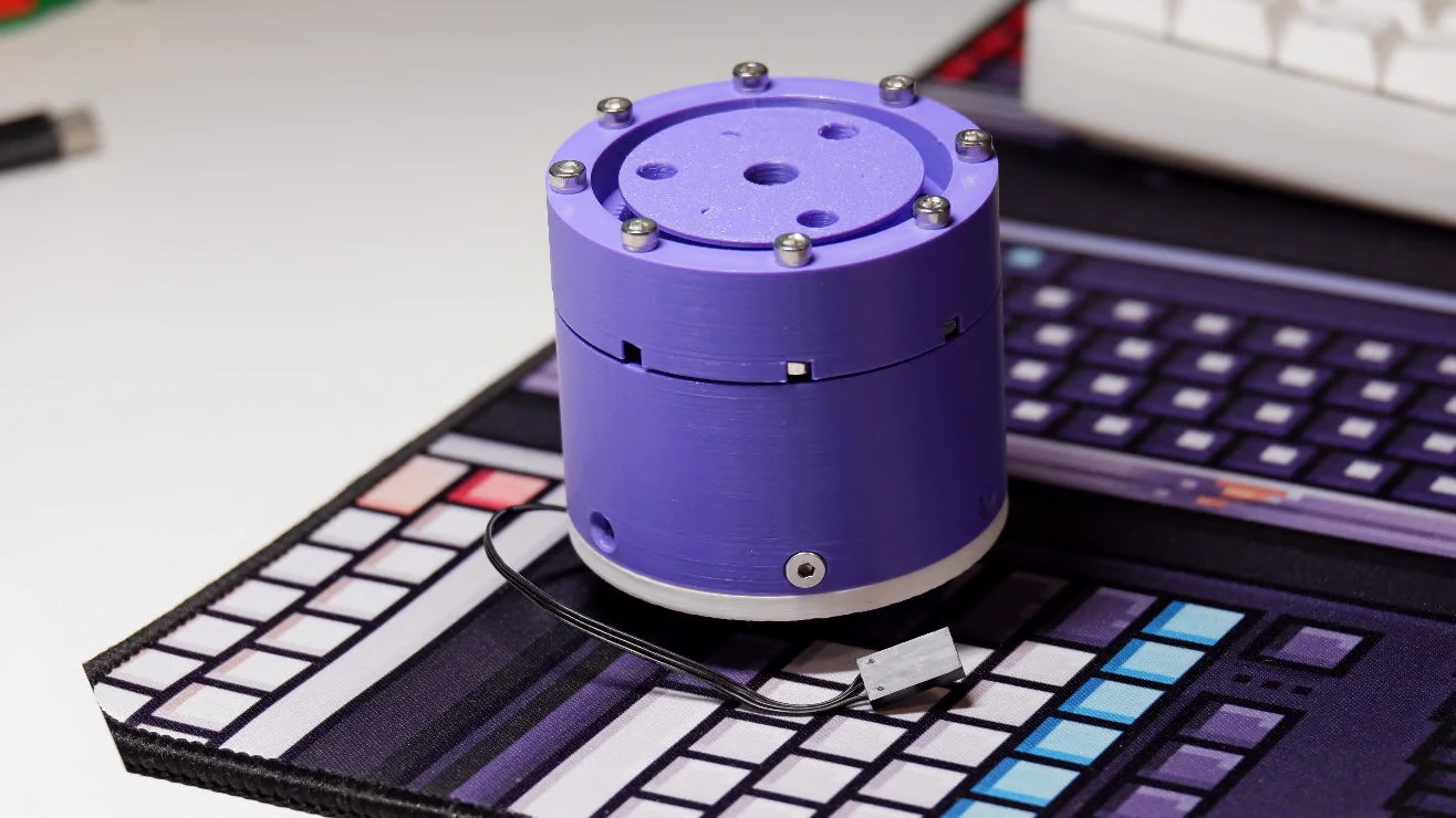
The cycloidal assembly exposed two packaging problems: excessive bearing variety and a large envelope. For the 2023 revision I moved to a bilateral planetary arrangement, which reduced bearing variety and the overall package size. The motor-driven sun gear and surrounding planets put the reduction into a coaxial package. I modeled the gears with SOLIDWORKS global variables and functions so related dimensions could change together instead of being redrawn independently.
Holding the assembly together along the shaft
A radial fit locates a part around the shaft; it does not necessarily stop that part sliding along it. The earlier assembly lacked sufficient axial constraint. I added flanges to prevent axial translation, giving the components defined locations through the shaft direction instead of relying on their radial fits to keep the mechanism together. That improved retention, but an actuator output also has to carry external loads in both axial directions. This distinction later became a central part of the bearing choice in CORActuator.
The 2023 actuator in numbers
| Feature | My prototype |
|---|---|
| Reduction | 40:1 bilateral planetary gearbox |
| Motor | 5010 BLDC |
| Part count | 20 parts, excluding fasteners |
| Historical build cost | Under USD $30 per actuator |
| Calculated stall torque | 16 Nm, theoretical rather than measured |
The torque calculation remains a sizing estimate. Physical testing established backdrivability: the output could drive the mechanism back through the transmission. That behavior matters for a joint that must respond to contact forces. It does not establish the output torque, backlash, or endurance, which require separate loaded tests.
What carried into the next design
The prototypes established concrete requirements for the next joint: fewer bearing types, explicit axial retention, and friction testing early in the build. Those lessons informed CORA, which develops the transmission, sensing, and control as one assembly.
TODOs
- Measure output torque and backdriving torque across the rotation range.
- Quantify backlash and repeatability in both directions under load.
- Run an endurance test and inspect the printed teeth, bearings, and axial retention for wear.
- Reduce friction and mass, then compare the revised parts against the existing assembly using the same tests.