Legged robotics · Kinematics
12-DOF quadrupeds
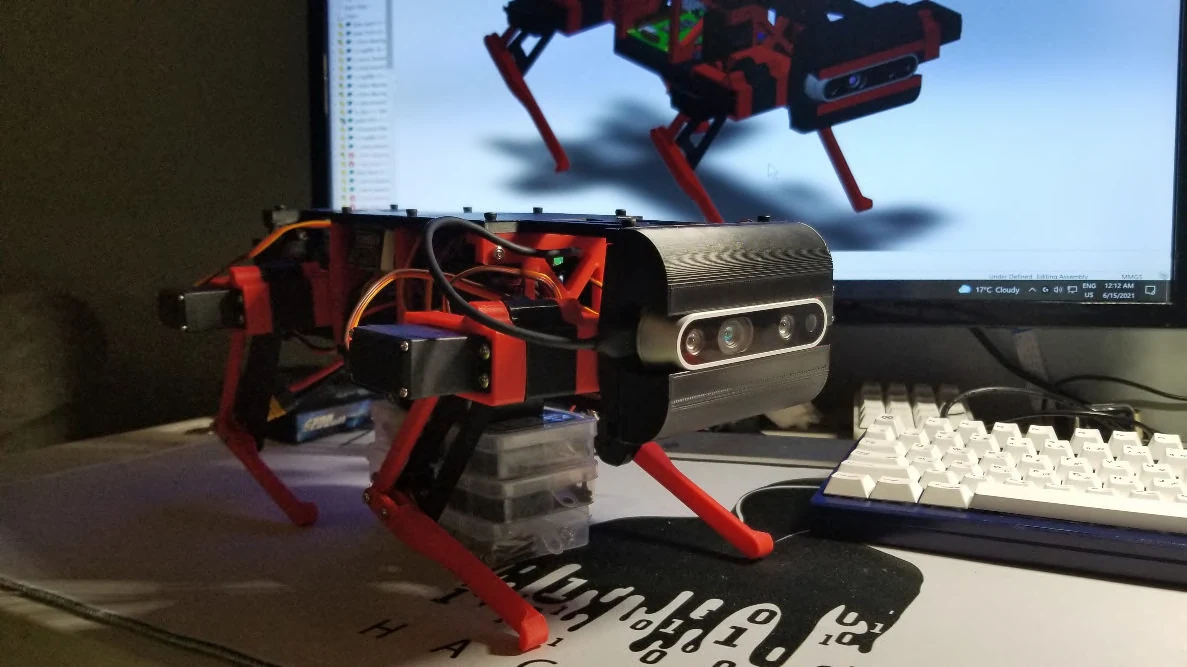
Two 12-DOF servo quadrupeds: a walking and turning Wi-Fi-controlled team build, followed by a lighter-packaged chassis with a RealSense camera.
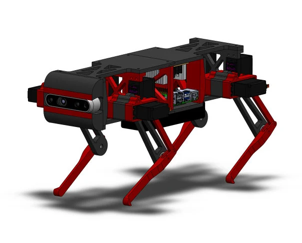
Mechanical design, printed parts, electronics integration, and inverse-kinematics gaits. The first robot was a team project, credited in the linked repository.
Overview: learning the whole legged-robot system
A quadruped makes the interaction between mechanics and control difficult to ignore. The robot has to support its own mass, place each foot, and move through a gait without overloading the joints. These two builds were an affordable way to work through that complete system using 12 servo-driven degrees of freedom and printed structural parts.
The first version was a team project focused on walking and turning. The second carried that foundation into a revised chassis with better component placement and a camera for future perception work.
Version one: turning foot trajectories into joint commands
Commanding the servo angles directly makes it difficult to describe where a foot should move. For the first robot, I developed inverse kinematics to work in the opposite direction: define a foot position, then calculate the joint angles needed to reach it. Pre-planned gaits supported walking, basic turning, and Wi-Fi control. This was a team build; the Spidey project repository preserves the earlier collaboration.
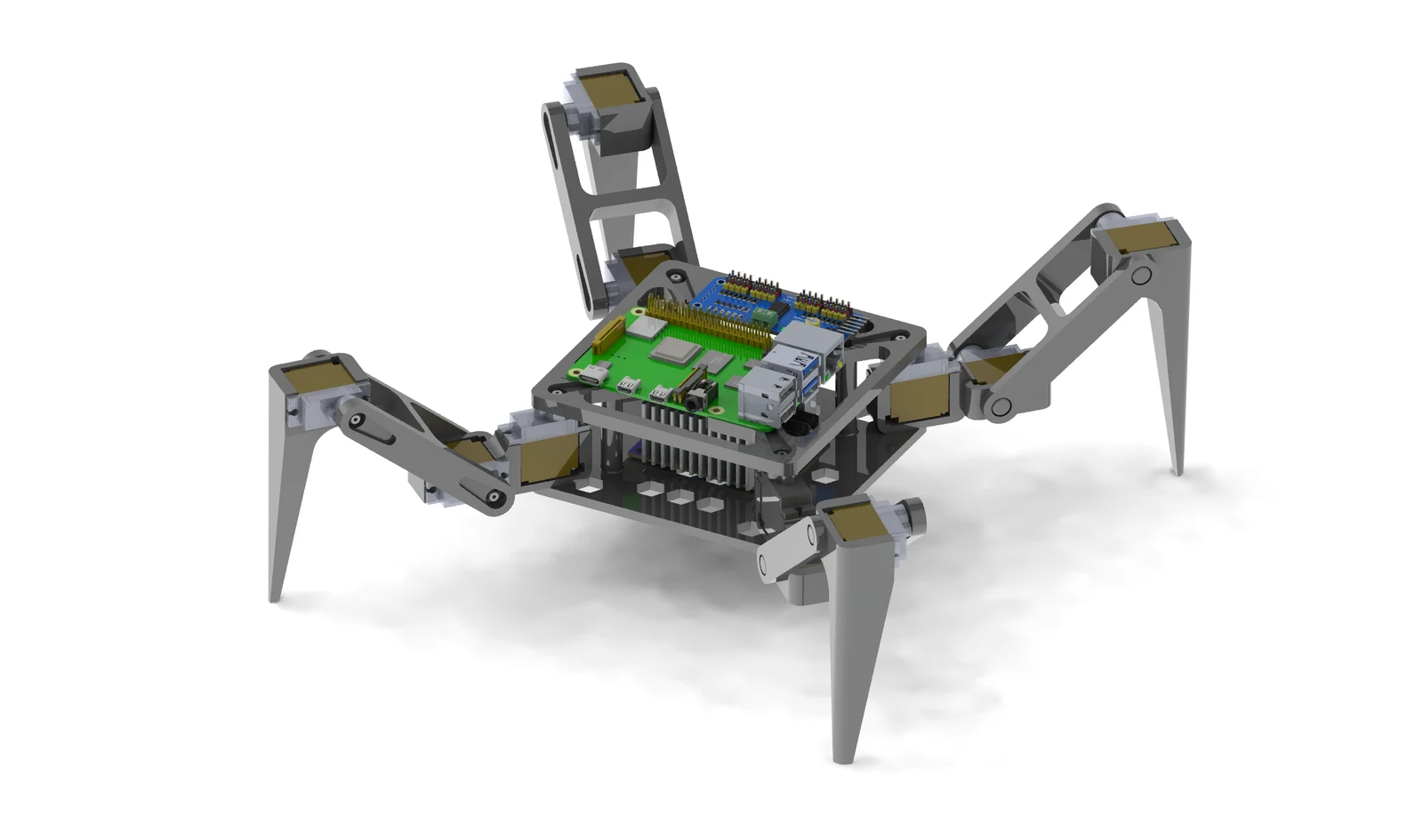
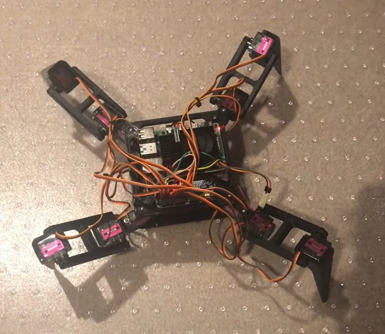
The first build cost less than CAD $150. Its walking tests established the mechanical priorities for the second chassis.
Version two: design around the weight
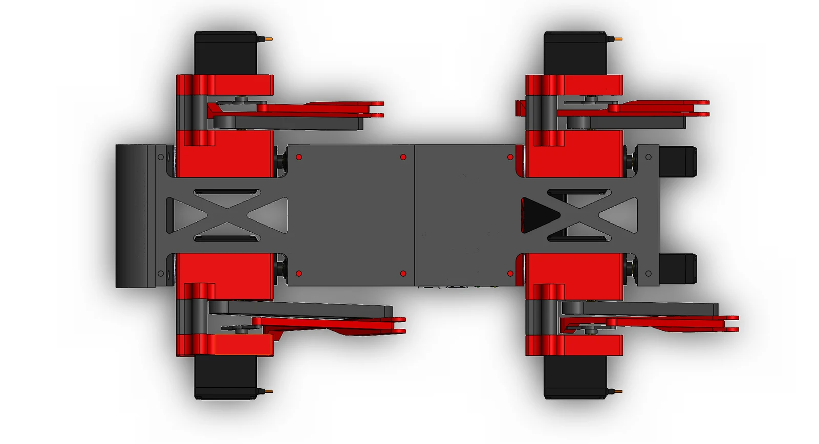
The first robot made it clear that selecting a servo was not enough; its load depended on how the rest of the robot was arranged. The battery and servos dominated the weight, so I changed component placement as well as the printed geometry. I moved the battery toward the bottom of the body and worked on the strength-to-weight ratio of the structural parts. The objective was to put mass where the chassis could support it efficiently, while keeping the leg geometry and electronics accessible for assembly.
Making room for perception
The second version reused the inverse-kinematics foundation and added a front-mounted RealSense camera for perception and future navigation work. Adding the camera created a physical platform for that work; it did not by itself create autonomous navigation. The completed hardware could stand under its own weight, while the more advanced gait and perception software remained in development.
What the two builds established
| First version | Second version | |
|---|---|---|
| Mechanical platform | Printed, 12-DOF servo quadruped | Revised printed structure and component placement |
| Demonstrated behavior | Walking and turning through pre-planned gaits, with Wi-Fi control | Standing under its own weight |
| Historical cost | Under CAD $150 | Under $250 excluding the camera, as recorded in my original build notes |
| Development focus | Electronics and inverse kinematics | Weight distribution, limb loading, and camera integration |
TODOs
- Finish transferring and tuning the walking and turning sequences on the second chassis.
- Measure joint loading and servo temperature through stance and swing before increasing gait speed.
- Run a repeatable walking test to compare stability, runtime, and power use between revisions.
- Integrate camera measurements into the control software after establishing reliable locomotion; reinforcement-learning gaits remain a separate next step.