Experimental hardware · Optimization
FDM Printing Optimization
An instrumented Prusa MK3S combining load cells, camera measurement, and a particle-swarm workflow for automated print calibration.
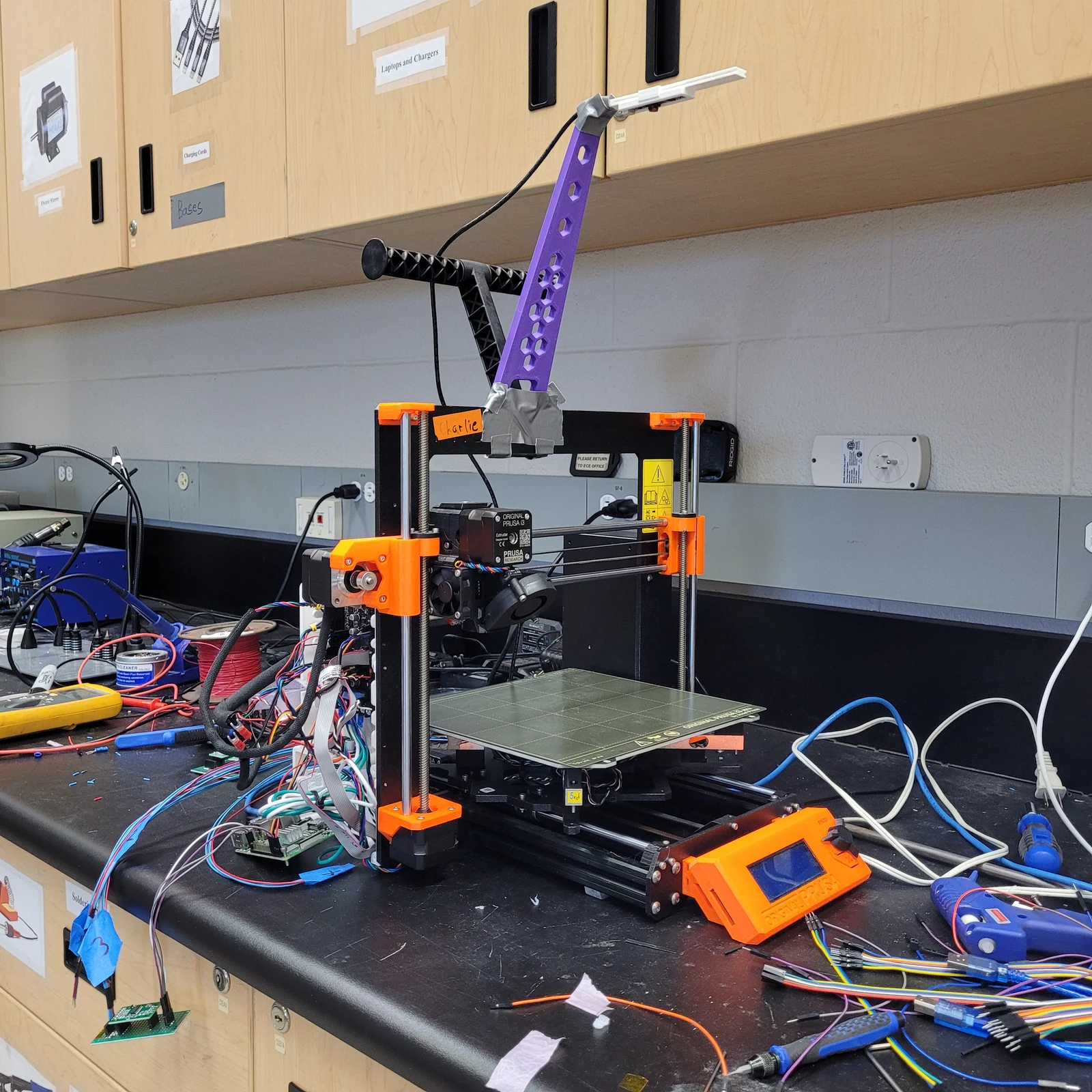
Sensor mounts, load-cell and camera integration, initial hardware tests, and G-code/optimization workflow development at FAST Lab.
Overview: closing the print–measure–adjust loop
Printer calibration often depends on a person repeatedly choosing settings, printing a test, inspecting it, and deciding what to change. I wanted to turn that into a repeatable experiment where the printer could measure its own output and use the measurement to choose the next settings.
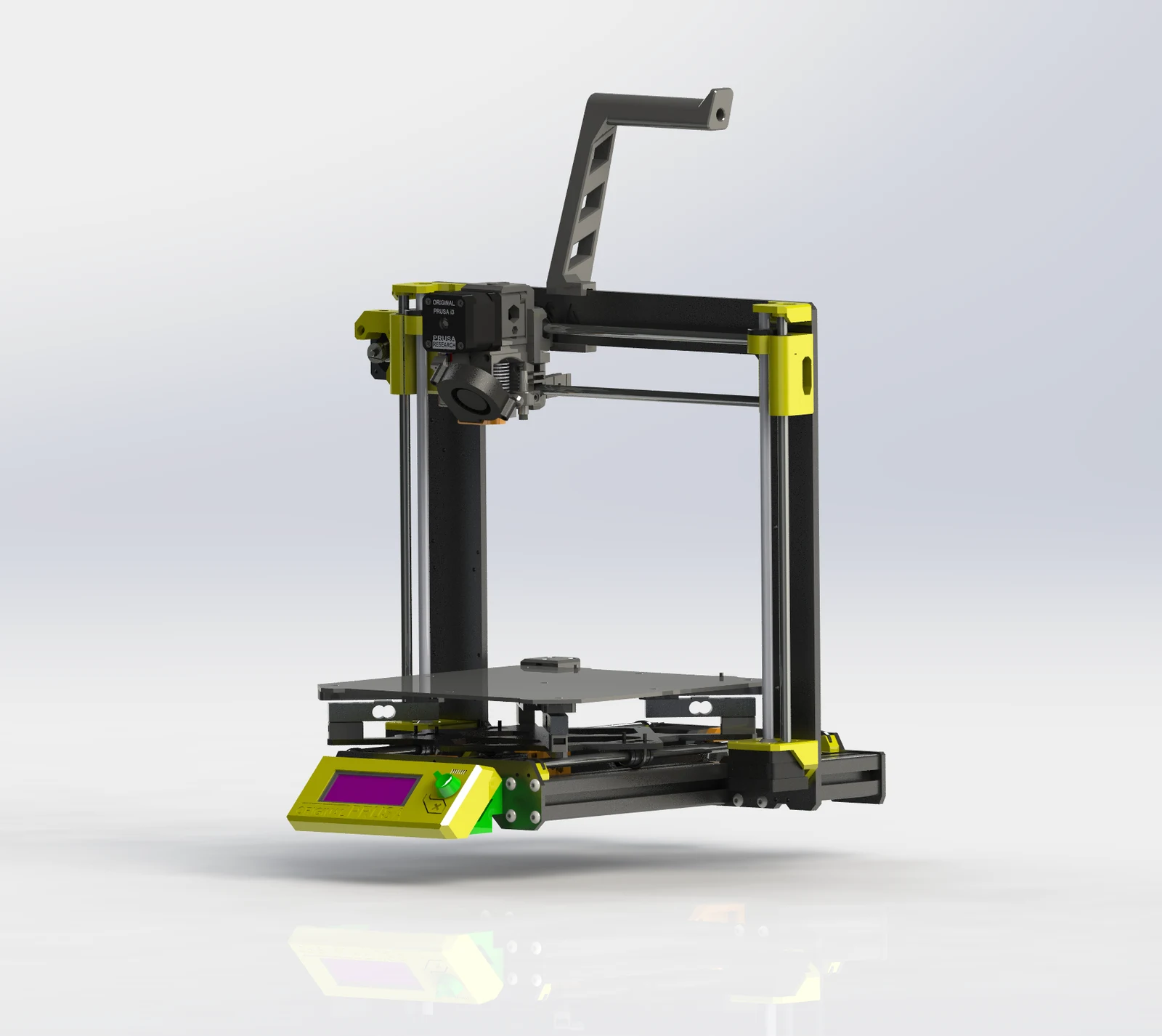
The prototype adds load cells and a camera to a Prusa MK3S through custom printed mounts. Starting with an existing machine kept the work focused on measurement and feedback. The hardware and initial sensor tests are complete; the dimensional-measurement and optimization integration remain in development.
The original add-on hardware budget was about CAD $150, excluding the printer. The add-on arrangement keeps the measurement system independent of a purpose-built printer.
Two measurements, two different problems
Load cells measure print mass, with readings averaged between iterations. The camera was intended to measure printed dimensions, using the bed dimensions as the initial pixel-to-length reference. Mass and dimensions answer different questions. A print can contain the expected amount of material but still have the wrong shape, so a mass measurement alone is not a complete calibration objective. Combining the two measurements is intended to distinguish deposition error from dimensional error.
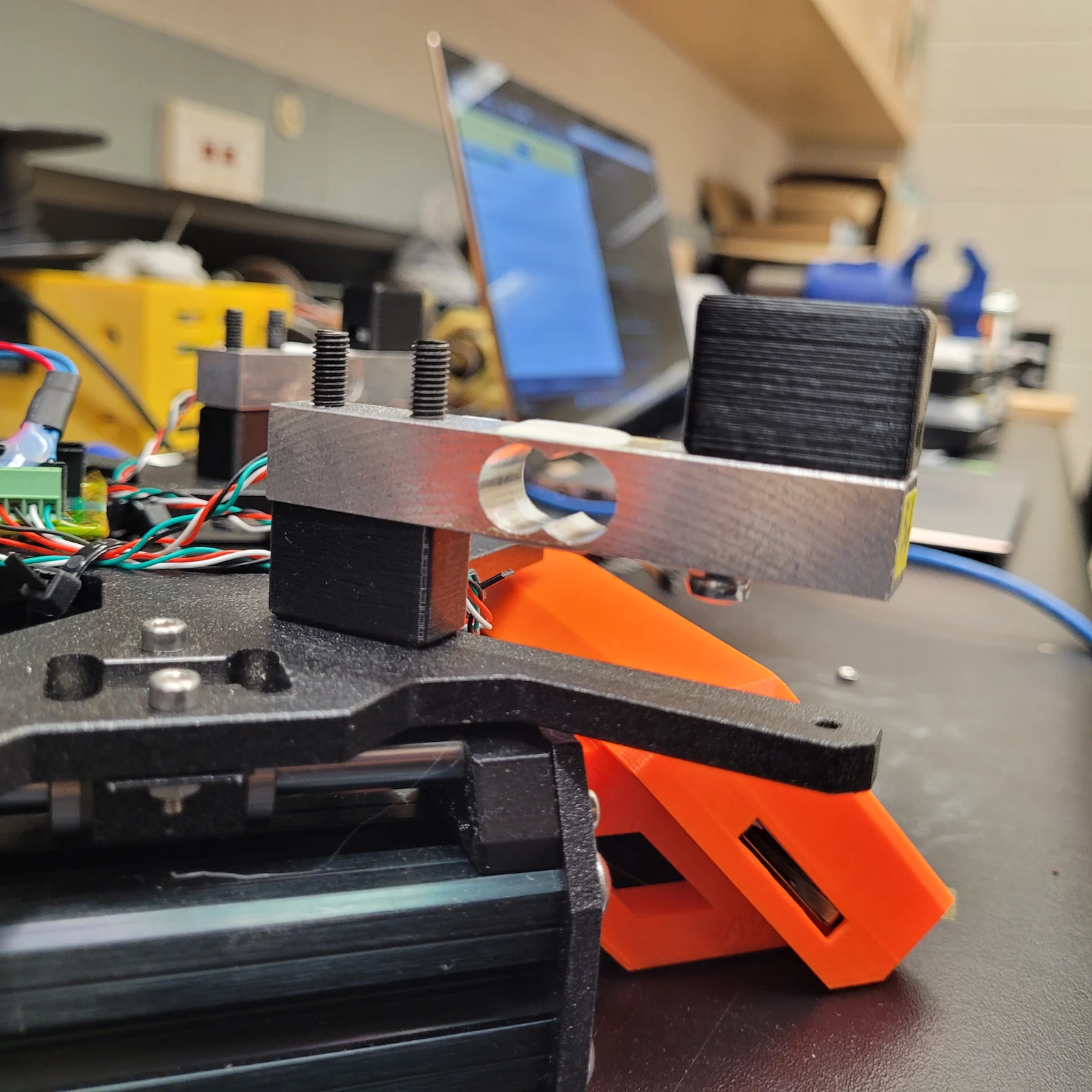
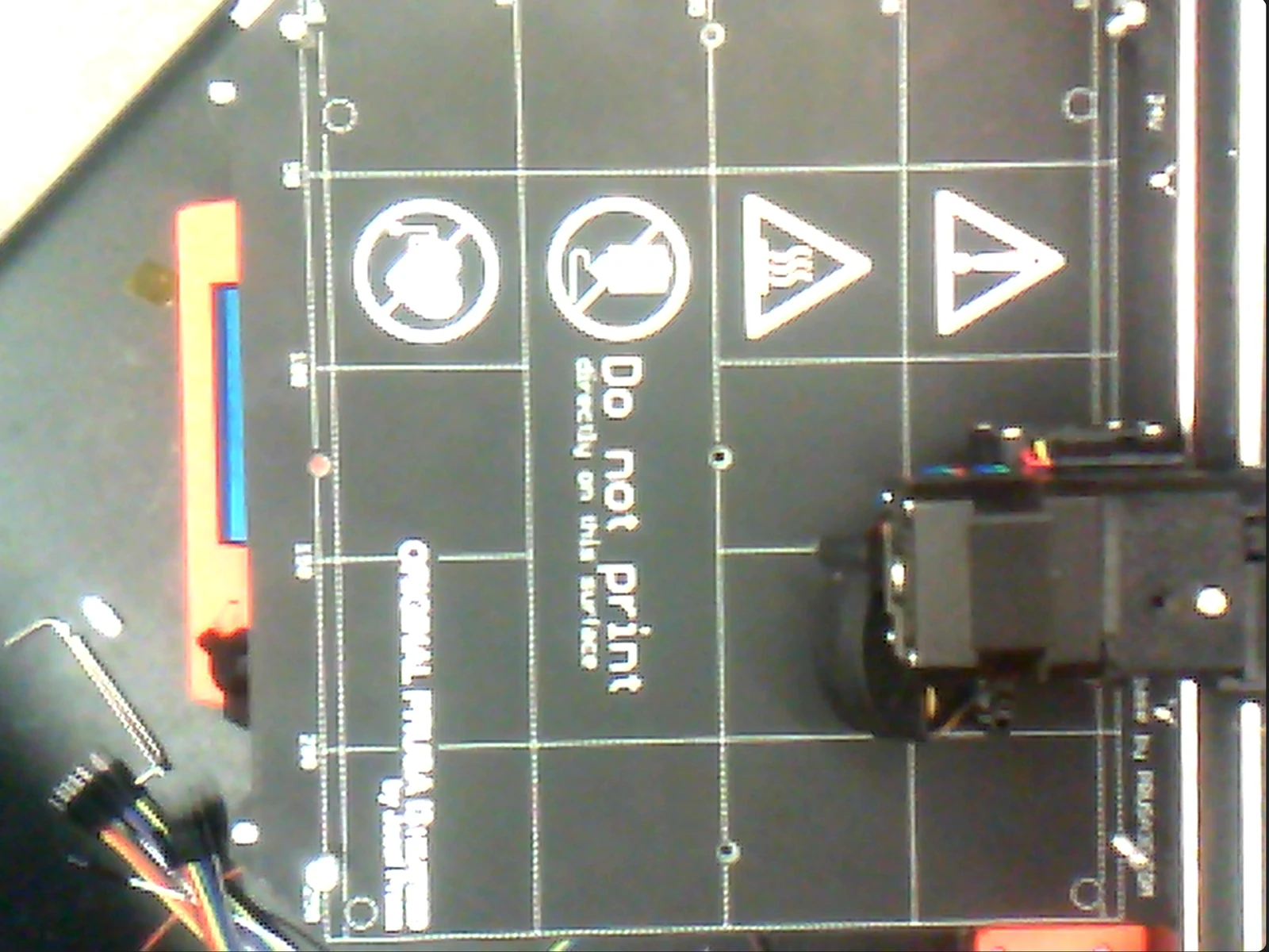
The mechanical assembly and initial load-cell and camera tests were completed. The difficult part is making the camera measurement reliable enough to drive an optimizer. A pixel-to-length scale estimated from the bed is a starting point, but it must be checked across the image and compared with an independent measurement. Otherwise, the software could optimize for a camera error instead of a better print.
Turning a measurement into the next print
The workflow uses particle swarm optimization (PSO), adapted from the prior study cited in the project repository. PSO treats candidate parameter sets as a population and uses their measured performance to guide later candidates. In this workflow, each candidate has a physical cost: a print has to finish before its result can be evaluated. An initial parameter set generates the first calibration sequence; the measured result informs the next candidate and its G-code. The sequence stops when the result is acceptable or the iteration limit is reached.
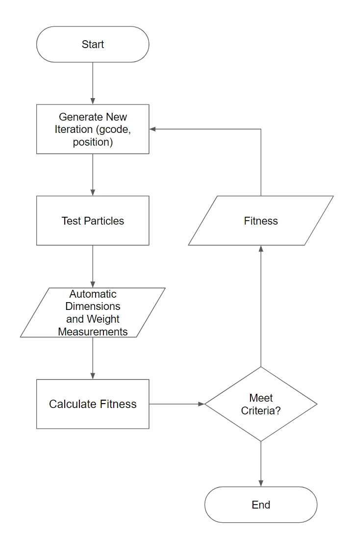
The software supports line, plane, and cube calibration modes, with a Raspberry Pi coordinating the process. The current script prompts the operator to remove each sample before the next trial. Before a sequence, the load cells are calibrated so a sensor offset does not become an apparent printing error. Failed prints also need an explicit outcome: a missing or incomplete part cannot be treated as just another numerical sample.
The result is a built measurement platform with tested sensors and a partially implemented optimization loop. Demonstrating autonomous improvement in print quality depends on completing dimensional measurement and PSO integration.
TODOs
- Finish camera-based dimensional measurement and compare it with caliper measurements across the bed.
- Complete the PSO integration, including parameter bounds, termination criteria, and recovery from failed prints.
- Define a repeatable objective that accounts for mass and dimensional error without hiding one behind the other.
- Compare optimized settings with the starting profile over repeated benchmark prints.
- Finish the wiring diagram, calibration instructions, and experiment documentation before adding the optional web interface.