Electromagnetics · PCB design
PCB axial-flux motors
A 20 mm motor concept for robot fingers, with parametric PCB windings, field analysis, and a compact dual-rotor prototype package.
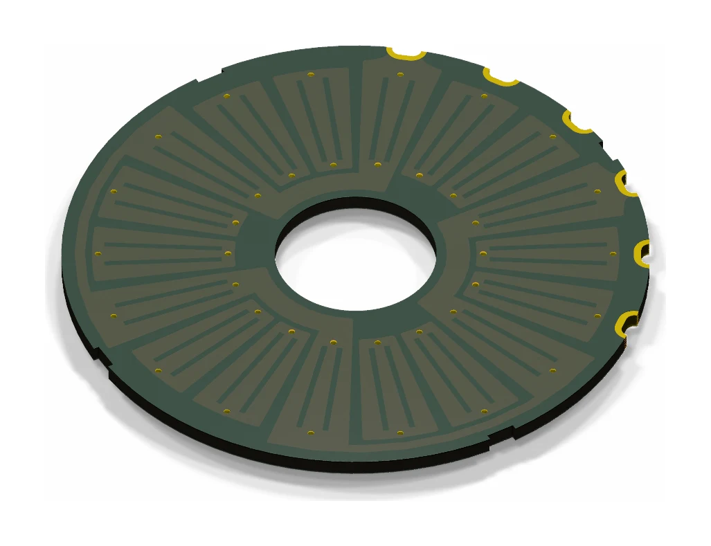
Parametric winding generation, electrical and magnetic analysis, design comparison, and the KiCad/CAD fabrication package.
Overview: fitting actuation into a robot finger
A dexterous hand must fit actuation, sensing, wiring, and structural support into a small volume. Locating an actuator closer to a finger joint can shorten the transmission path, but it leaves very little room for the motor. Holding a grasp also demands useful torque at low speed, where heat rejection becomes a major constraint.
A large motor with a remote transmission can move the problem out of the finger, but it adds another mechanical path to package. I wanted to explore the alternative: a 20 mm motor package for a finger-joint actuator, with the winding geometry and manufacturing process designed around that space from the start. A flat axial-flux layout creates space around the shaft and allows winding thickness to be adjusted by stacking boards. My focus is on a motor that can be manufactured repeatably, integrated into a joint, and characterized under the holding and running conditions that matter for a hand.
Moving winding manufacture onto a PCB
Custom miniature BLDC inrunners can be expensive to source and difficult to manufacture: fine-wire placement, insulation, and precision stator construction become harder as the motor shrinks. PCB windings move conductor placement into a repeatable fabrication process, with editable geometry and layer interconnections specified in the board files. For this project, that makes winding geometry something I can revise and send for fabrication instead of rewinding by hand. Whether the complete actuator is cheaper still depends on the board process, magnets, mechanics, and assembly.
PCB construction still imposes constraints. Copper thickness, return-path resistance, via current density, and insulation consume space; thin multilayer boards require fabrication review. Advanced HDI processing can also be expensive. The objective is to establish what a comparatively accessible six-layer process can deliver before moving to a more specialized stack.
The principal reference: high-density PCB actuation
Wang and colleagues’ 2025 paper, High Torque Density PCB Axial Flux Permanent Magnet Motor for Micro Robots, is the central technical reference. It identifies winding fill as a bottleneck below 20 mm and demonstrates four 12-layer HDI modules, totaling 48 copper layers, at 19 mm diameter and approximately 45% copper fill. The authors report 23.4 mNm continuous stall torque from their prototype.
Their motor retains a steel stator core and uses two stators around one rotor. My design takes a different route: a coreless winding stack between two rotors, built from six-layer modules. The paper establishes the potential of dense PCB windings; its fabrication process, magnetic circuit, and reported performance are not interchangeable with this prototype. Its emphasis on low-speed thermal testing is especially relevant to the next bench work. Paper and experimental results.
Earlier axial-flux builds
Shane Colton’s 2009 Epic Axial Motor update shows how winding access and termination details shape a build. The split copper-strip winding brought both ends to the outside, simplifying interconnection. It is a much larger wound motor, but the construction problem is relevant: active copper only helps if its connections can be assembled.
The DIY Toroidal Axial Flux PM build documents another hands-on route through wound stators and fabricated rotor structures. Together, these earlier projects provide practical context for winding construction and iteration; the miniature PCB approach follows a different manufacturing process.
Selecting the magnetic arrangement
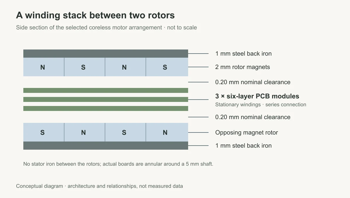
The dual-rotor arrangement places permanent magnets on both sides of the active copper, with steel back irons closing the magnetic return path. Here, “axial flux” means that the working magnetic field crosses the winding plane along the shaft direction. Current in the radial copper traces interacts with that field to produce tangential force. With no stator teeth or core, the design work concentrates on useful radial copper, resistance, magnet utilization, and an air gap that can be assembled repeatably.
One winding definition, from analysis to KiCad
A winding that looks good in a drawing still needs a complete current path. I use a single parametric definition for previews, geometry validation, electrical calculations, and KiCad export so a layout change carries through all four. The six-layer winding has tapered copper lanes: the lanes widen toward the outside radius while preserving the physical gap between them. All three phases have active copper on all six layers; each phase’s return paths occupy a symmetric pair of layers.
Only part of each conductor is positioned to contribute useful torque. The return paths still carry current and dissipate heat, so adding copper without checking the full circuit can make an attractive layout less useful electrically. Return-path resistance and heating therefore remain part of the model, alongside the active copper. Endpoint vias equalize the repeated conductors across the board, while the inter-board harness determines whether modules operate in series or parallel.
Prototype selection: reduce the stack and simplify wiring
The current package targets a 20 mm rotor diameter and 5 mm shaft. The candidate study compared a corrected five-board baseline with three- and four-board stacks. The finalists use the same rotor parts and nearly the same PCB geometry; the important decisions are the number of modules, endpoint-via arrangement, and wiring.
| Dimension or connection | Corrected baseline | Selected prototype |
|---|---|---|
| PCB stack | Five 0.80 mm boards | Three 0.61 mm boards |
| Copper layers per board | 6 | 6 |
| Rotor–stator sandwich | 14.88 mm | 8.39 mm |
| Magnet dimensions | Ø6 × 3 mm | Ø6 × 2 mm |
| Steel back iron per rotor | 2 mm | 1 mm |
| Phase connection | Five parallel modules | One series string of three modules |
The selected stack is 6.49 mm shorter than the baseline. The wiring choice was as important as the stack height. Parallel module strings create another path for circulating current when their induced voltages differ. Connecting the three modules in one series string removes that inter-string path. Eddy currents within each board remain in the loss model.
Comparing torque within explicit thermal limits
Analytical and unwrapped 2D FEMM models supported initial iteration. The candidate comparison then used finite 3D field and electrical analysis, with checks on mesh and boundary sensitivity, flux-derived torque, copper refinement, and loaded operating points.
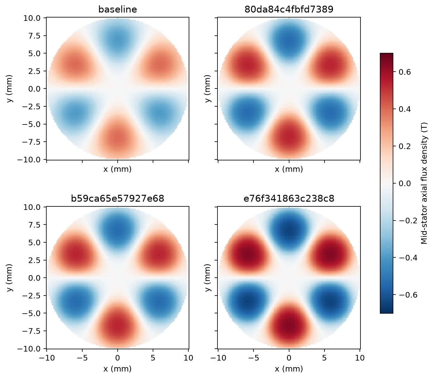
At 450 rpm, 40 °C ambient, and an assumed 200 °C/W external thermal resistance, the selected design models 0.431 mNm running torque and 0.1635 mNm/cm³ of rotor–stator sandwich volume. That is 2.49× the corrected baseline’s modeled torque density. The comparison uses the selected N45 magnets’ 80 °C ceiling and the baseline’s conservative 60 °C ceiling; using a common 60 °C ceiling reduces the density ratio to about 1.54×.
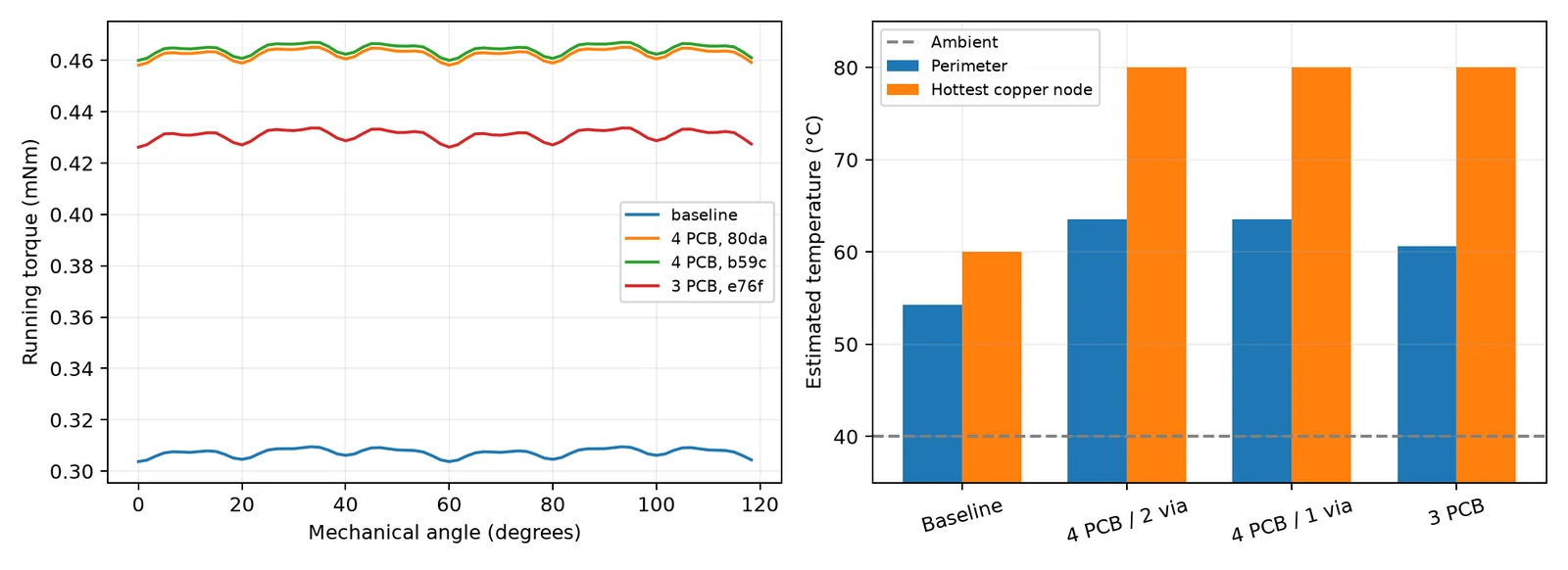
A small modeled advantage is not useful if it is smaller than the uncertainty in the build. The finalists are within 1% of one another in modeled density, so I selected the three-board version for its shorter stack and simpler series wiring. Differences this small in modeled density do not establish a unique optimum.
Closing the gap between a model and a build
The package includes editable KiCad and mechanical CAD, Gerbers and drills, an explicit stackup, phase interconnections, and measurement procedures. The 0.61 mm six-layer board requires a fabrication review; its thickness is a design callout, not a generic catalog assumption.
The nominal air gaps are 0.20 mm per side. Assembly therefore requires shimming from measured board, adhesive, and magnet-face dimensions. Rotor runout, shaft endplay, and magnetic attraction all consume that clearance. The low winding inductance also makes current ripple and minimum PWM pulse width a driver-design problem that must be resolved on hardware.
TODOs
- Confirm the thin six-layer stackup and copper balancing with the fabricator, then measure the finished boards before setting rotor spacing.
- Measure phase resistance, back-EMF, and locked-rotor torque; verify the phase-C terminal reversal before energizing the stack.
- Validate the intended current-controlled drive against phase-current ripple and heating assumptions.
- Measure enclosed holding/running temperatures and hot magnetic flux before assigning a continuous rating.
- Measure gearbox efficiency, friction, and backlash separately from motor performance; the quoted density covers only the rotor–stator sandwich.