Mechanism design · Food printing
Pastruder
A geared peristaltic extruder for viscous paste, tested with a 60% bean-powder formulation and integrated into a four-extruder printer.
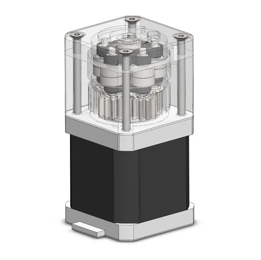
Pump and planetary-gearbox design, physical prototyping, paste testing, and four-extruder printer integration at FAST Lab.
Overview: printing material that does not behave like filament
Paste printing needs a different feed mechanism from a conventional filament printer. Instead of pushing a solid strand into a hotend, the machine has to meter viscous material through a tube. At FAST Lab, I developed Pastruder around a peristaltic pump so the paste could remain inside a replaceable feed path.
The mechanism uses rotating rollers to squeeze a silicone tube against the housing. As that compressed region travels around the pump, it moves material through the tube. The drive parts do not need to contact the paste, but the pump now depends on how the flexible tube behaves under compression.
Roller clearance: enough compression to seal the tube
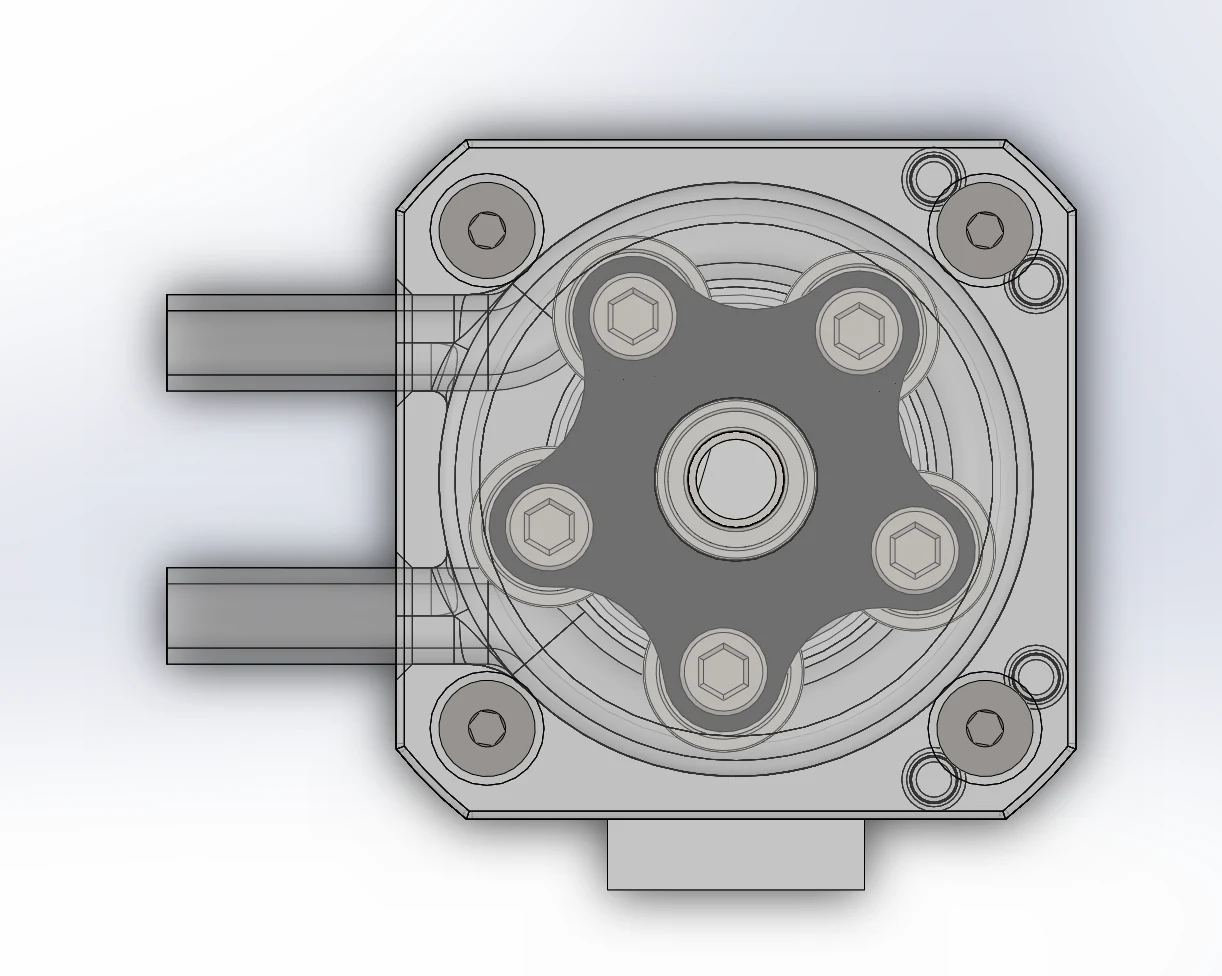
The important design variable was the clearance between each roller and the outer wall. Too little compression would not seal the tube and generate suction; too much compression increased friction and the load on the motor. This creates a real tradeoff: reducing friction by opening the gap can also remove the compression that makes the pump work. I used successive physical prototypes to establish a workable range before finalizing the drive.
A 3:1 gearbox resolved stepper slipping
The early mechanism demanded too much torque from the direct-drive stepper. Instead of loosening the tube compression and losing the seal, I added a compact 3:1 planetary reduction between the motor and rollers. The reduction trades roller speed for available torque. Keeping the motor, gearbox, and roller carrier on the same axis also avoided a separate belt or offset drive, which would have enlarged the pump assembly.
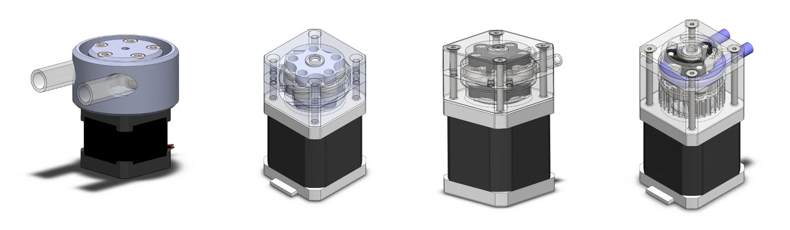
Trial builds established roller spacing and tube compression under load. The physical deformation of the silicone, especially during repeated squeezing, was the deciding factor. CAD established the nominal gap, but the assembled tube showed whether that gap was actually usable.
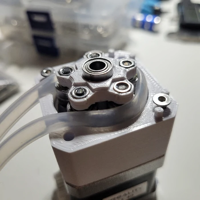
From a pump to a four-material printer
The pump successfully extruded a viscous bean-powder paste containing 60% powder. A subsequent retrofit added four extrusion units to a commercial 3D printer, with separate tubes feeding multiple paste materials to the printing area.
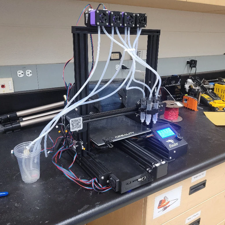
Integration demonstrated multi-material paste printing. The remaining question is how accurately a motor command controls deposited material. Tube deformation, paste formulation, and the length of each feed path can affect the response, so each unit needs its own mass-per-revolution and start/stop characterization.
TODOs
- Calibrate delivered mass per motor revolution for each paste formulation and tube size.
- Measure startup delay and residual flow after stopping, then compensate for them in extrusion commands.
- Run repeated extrusion cycles to measure tube wear and check whether the roller clearance needs adjustment over time.
- Compare the four feed paths under the same command sequence to quantify material-switching delay and unit-to-unit variation.