Sensing · Electronics
Magnetic encoder development
Custom magnetic encoder hardware and firmware for calibrated rotary feedback, developed around the hollow-shaft packaging of compact actuators.
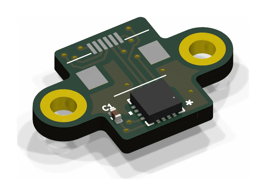
PCB design, embedded angle acquisition, calibration, and communication experiments.
Overview: measuring angle without blocking the shaft
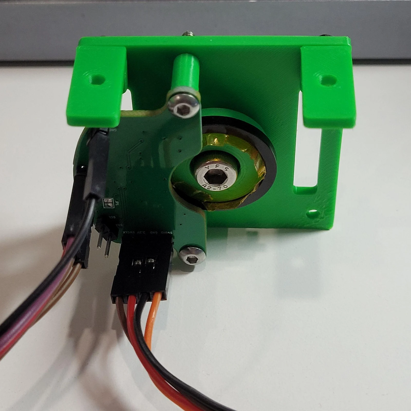
A common rotary-sensing arrangement places a magnet and sensor on the shaft axis. That becomes inconvenient when the same space is needed for cables to pass through a robotic joint. I developed these encoder boards alongside the actuators so the sensing arrangement would fit the mechanism from the start.
Moving the sensor off-axis solves a packaging problem, but changes the magnetic geometry. The board can fit perfectly and still report an inaccurate angle if the magnet position, signal shape, or calibration is wrong. The project therefore includes both the physical sensor arrangement and the firmware needed to interpret it.
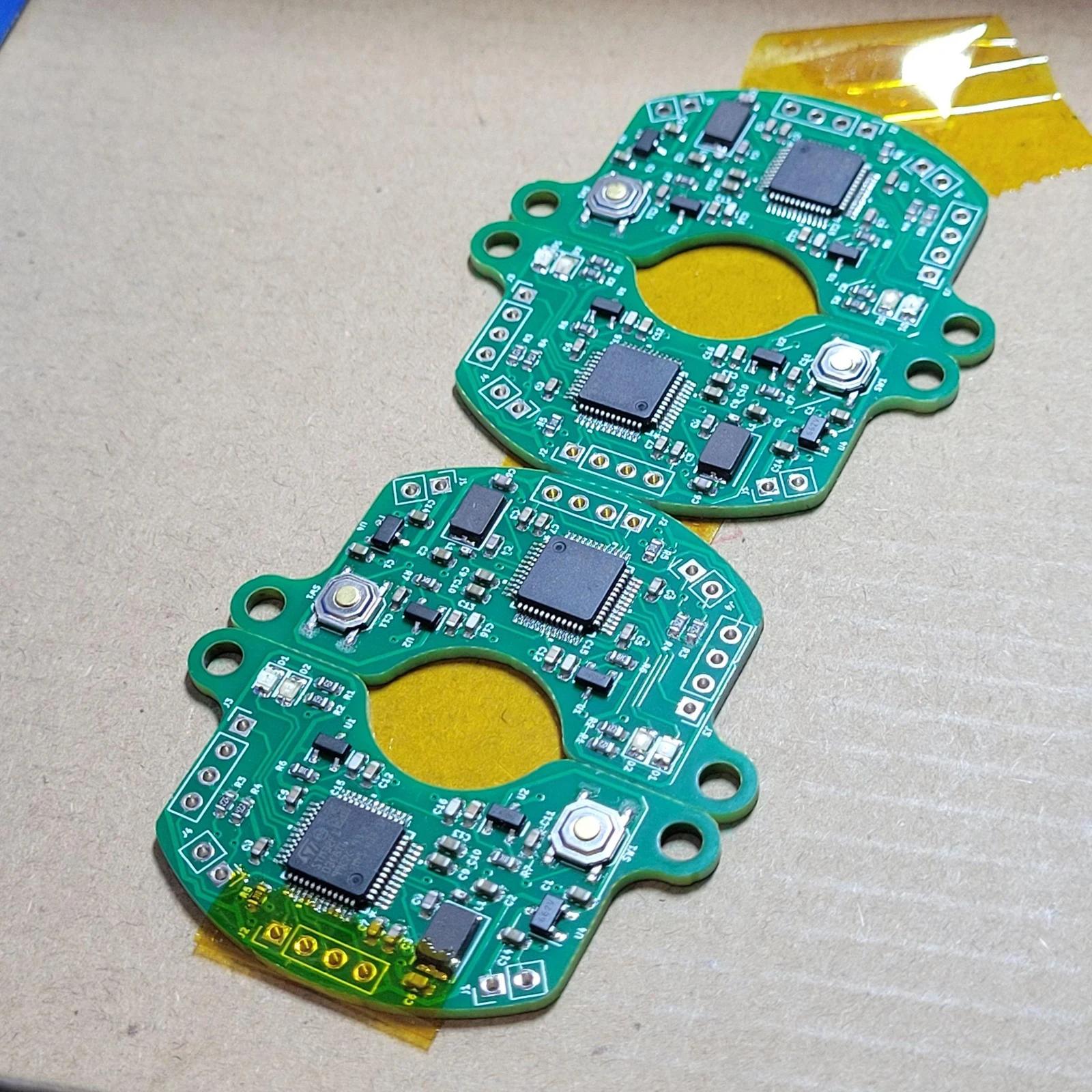
The iterations include a magnetic-encoder board, an off-axis layout, and a separate MA732-based design in the CORA hardware collection. Paired PCB and mechanical exports support fit checks against the joint assembly.
Why two analog channels are useful
A sine channel alone does not identify a unique angle throughout a revolution: the same value occurs at more than one position. Adding a cosine channel makes the pair useful for determining angle and direction. The practical problem is that real channels have offsets, different amplitudes, and noise.
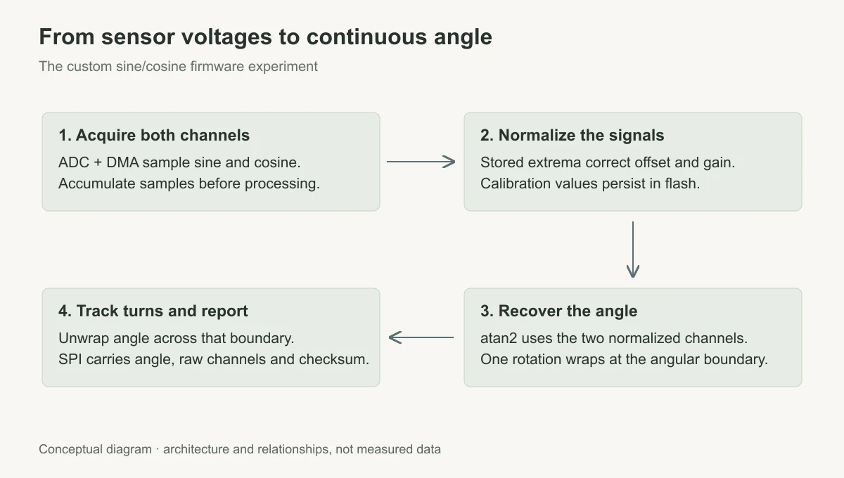
One firmware experiment uses an STM32F103 to acquire both channels through ADC and DMA, which transfers samples without handling each one in software. Samples are accumulated before angle calculation, then normalized using stored calibration bounds. An atan2 approximation recovers position, with wrap tracking to report continuous angle across complete turns.
Filtering and dead-band logic address small changes near a transition, while calibration handles channel offset and gain differences. Acquisition and communication also need a consistent view of the latest sample, which makes shared interrupt state part of the design.
Calibration that can be inspected from the host
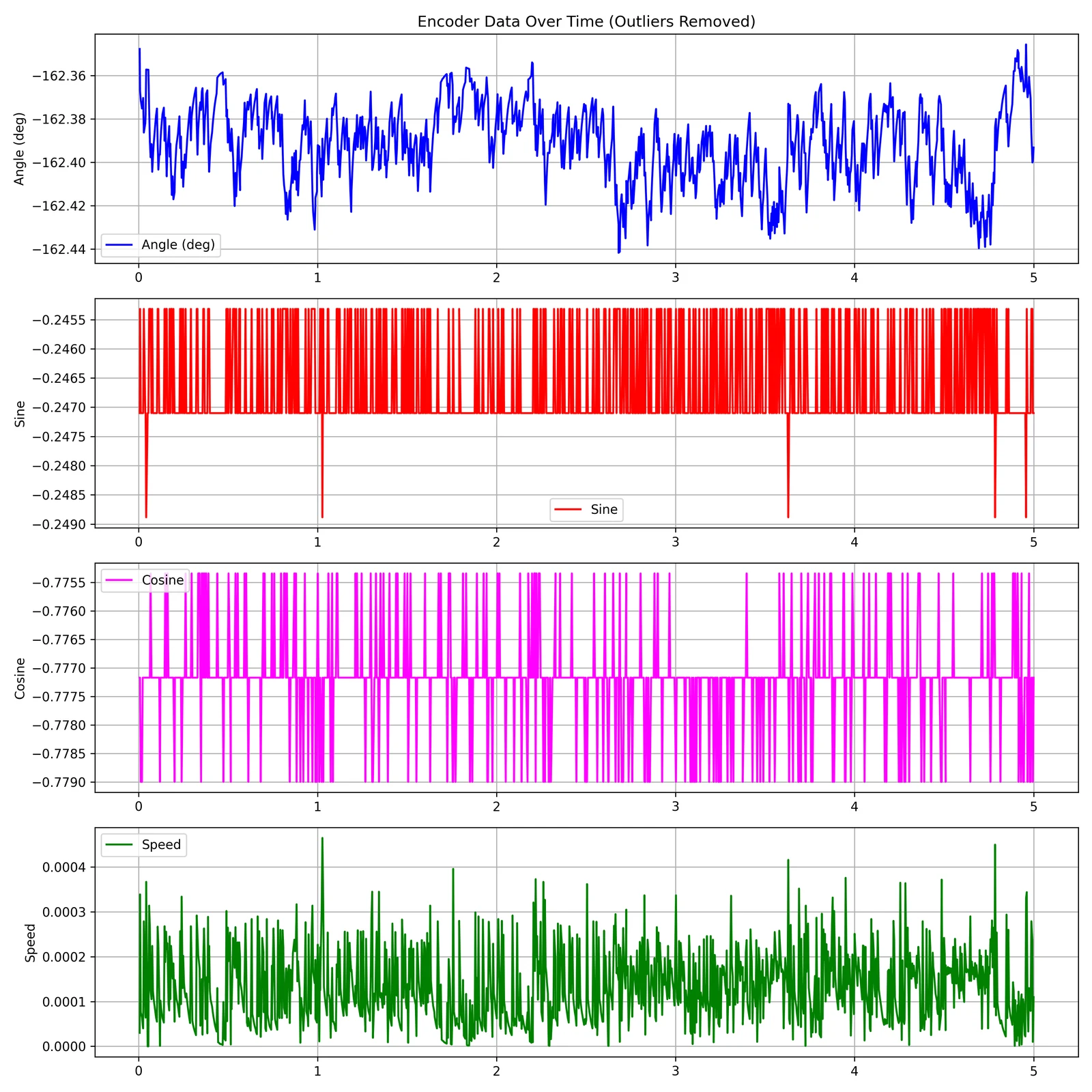
Calibration commands collect channel extrema and persist the resulting bounds in flash. The SPI response contains the continuous angle and the sine/cosine values, with a frame header and checksum. An angle value by itself hides most of the useful debugging information. Sending the channels alongside it makes it possible to distinguish a poor calibration from a wiring or magnet-alignment problem.
Bringing the firmware interfaces under control
I also ported an embedded exercise to Rust to work through peripheral setup and interrupt-driven acquisition. That version still uses substantial low-level register access and shared state. The next revision needs clearer ownership of the acquisition buffer and a documented timing relationship between sampling and SPI reporting. A working angle estimate is the starting point; accuracy, latency, and behavior during reversals are the measurements needed to qualify it for a joint.
TODOs
- Measure absolute angle error against a reference encoder through a full rotation, in both directions.
- Repeat the sweep at different magnet offsets and gaps to separate alignment sensitivity from repeatability.
- Measure acquisition-to-SPI latency and check angle unwrapping during rapid reversals.
- Replace channel-extrema calibration with a fitted correction if reference measurements show that offset/gain compensation is insufficient.
- Refactor interrupt-shared state and document the calibration procedure so a new board can be brought up consistently.