Electromagnetics · Team engineering
Linear induction motor
Double-sided linear induction motor development with Western Trillium Hyperloop, connecting electromagnetic simulation, component selection, and prototype hardware.
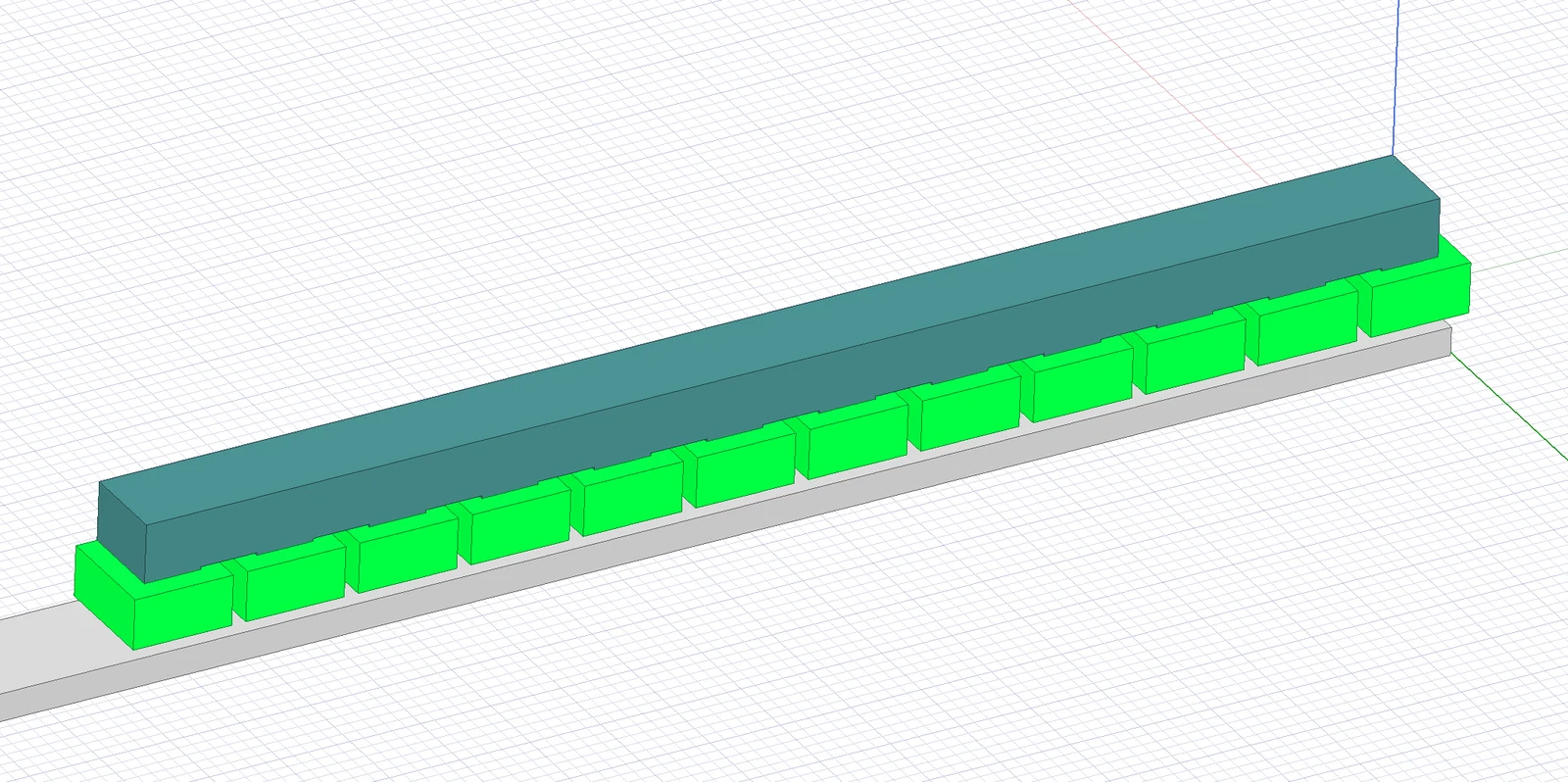
Motor design, ANSYS Maxwell analysis, component selection, and bill-of-materials development with Western Trillium Hyperloop.
Overview: propulsion without a rotating output shaft
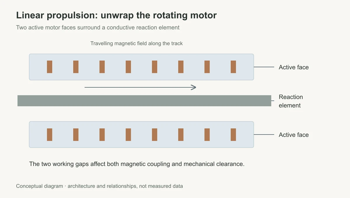
A rotating induction motor produces motion around a shaft. Conceptually unwrapping that geometry creates a travelling magnetic field along a track instead. The field induces currents in a conductive reaction element, and their interaction produces linear force. This was the propulsion approach explored by the Western Trillium Hyperloop team.
My work on the double-sided linear induction motor connected the electromagnetic model to the hardware we could build: the geometry, winding arrangement, power supply, and working gaps had to make sense as one system.
My contribution covered ANSYS Maxwell analysis, component selection, and the bill of materials. The electromagnetic model supported geometry studies while the team developed the physical prototype.
Why the working gaps matter
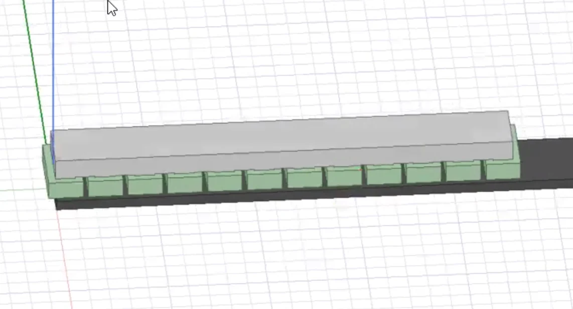
The design used four pole pairs and a 48 V battery supply. The double-sided arrangement placed active motor structures on both sides of the reaction element, so the mechanical layout and the working gaps were part of the electromagnetic design problem.
Reducing a working gap improves magnetic coupling, but also leaves less tolerance for alignment and movement. That is why I treated the mechanical gap as a model input rather than a dimension to settle after the electromagnetic design.
Litz wire was considered to reduce winding eddy-current losses; that construction remained a proposed revision. Selecting components and preparing the bill of materials brought the simulation work into a concrete prototype scope.
Turning the speed target into a test
The original project set a 200 km/h design target and planned a flywheel-based test. This phase produced design, simulation, and prototype hardware; measured thrust–speed characterization remained outstanding.
A speed target alone does not specify how much thrust is available to reach it. The next useful milestone is a controlled comparison between the model and prototype, recording the working gap, winding configuration, supply conditions, and temperature with each force measurement. That would show which assumptions survive the move from simulation to hardware.
TODOs
- Complete the flywheel-test arrangement and define how speed, reaction force, and electrical input will be measured.
- Finalize the winding construction and compare the proposed Litz-wire option with the baseline.
- Sweep operating conditions to measure thrust and temperature, then compare them with ANSYS Maxwell predictions.
- Use those results to revise the speed target and operating limits before extending the propulsion design.